

212 Beam-based Correction and Optimization for Accelerators
500
1000
1500
objective (um)
RCDS
0
50
100
150
evaluation
0
0.5
1
x
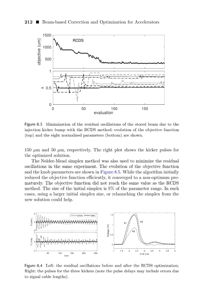
Figure 8.3 Minimization of the residual oscillations of the stored beam due to the
injection kicker bump with the RCDS method: evolution of the objective function
(top) and the eight normalized parameters (bottom) are shown.
150 µm and 50 µm, respectively. The right plot shows the kicker pulses for
the optimized solution.
The Nelder-Mead simplex method was also used to minimize the residual
oscillations in the same experiment. The evolution of the objective function
and the knob parameters are shown in Figure 8.5. While the algorithm initially
reduced the objective function efficiently, it converged to a non-optimum prematurely. The objective function did not reach the same value as the RCDS
method. The size of the initial simplex is 5% of the parameter range. In such
cases, using a larger initial simplex size, or relaunching the simplex from the
new solution could help.
-2
0
2
X (mm)
before
after
50
100
150
200
250
turn
-1
0
1
Y (mm)
1
1.5
2
2.5
3
3.5
4
4.5
5
time (us)
0
0.5
1
1.5
Voltage (kV)
K1
K3
K2
Figure 8.4 Left: the residual oscillations before and after the RCDS optimization;
Right: the pulses for the three kickers (note the pulse delays may include errors due
to signal cable lengths).
500
1000
1500
objective (um)
RCDS
0
50
100
150
evaluation
0
0.5
1
x
Figure 8.3 Minimization of the residual oscillations of the stored beam due to the
injection kicker bump with the RCDS method: evolution of the objective function
(top) and the eight normalized parameters (bottom) are shown.
150 µm and 50 µm, respectively. The right plot shows the kicker pulses for
the optimized solution.
The Nelder-Mead simplex method was also used to minimize the residual
oscillations in the same experiment. The evolution of the objective function
and the knob parameters are shown in Figure 8.5. While the algorithm initially
reduced the objective function efficiently, it converged to a non-optimum prematurely. The objective function did not reach the same value as the RCDS
method. The size of the initial simplex is 5% of the parameter range. In such
cases, using a larger initial simplex size, or relaunching the simplex from the
new solution could help.
-2
0
2
X (mm)
before
after
50
100
150
200
250
turn
-1
0
1
Y (mm)
1
1.5
2
2.5
3
3.5
4
4.5
5
time (us)
0
0.5
1
1.5
Voltage (kV)
K1
K3
K2
Figure 8.4 Left: the residual oscillations before and after the RCDS optimization;
Right: the pulses for the three kickers (note the pulse delays may include errors due
to signal cable lengths).