

210 Beam-based Correction and Optimization for Accelerators
8.2 STORAGE RING INJECTION KICKER BUMP MATCHING
The injection system of the SPEAR3 storage ring consists of three kickers
that are located in three consecutive straight sections. During injection, the
three kickers are powered by current pulses over a short period of time. The
corresponding kicks produce a horizontal orbit bump for the stored beam,
moving it toward the injected beam and facilitating the capture of the latter.
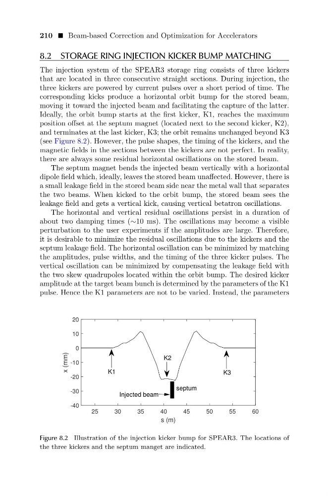
Ideally, the orbit bump starts at the first kicker, K1, reaches the maximum
position offset at the septum magnet (located next to the second kicker, K2),
and terminates at the last kicker, K3; the orbit remains unchanged beyond K3
(see Figure 8.2). However, the pulse shapes, the timing of the kickers, and the
magnetic fields in the sections between the kickers are not perfect. In reality,
there are always some residual horizontal oscillations on the stored beam.
The septum magnet bends the injected beam vertically with a horizontal
dipole field which, ideally, leaves the stored beam unaffected. However, there is
a small leakage field in the stored beam side near the metal wall that separates
the two beams. When kicked to the orbit bump, the stored beam sees the
leakage field and gets a vertical kick, causing vertical betatron oscillations.
The horizontal and vertical residual oscillations persist in a duration of
about two damping times (∼10 ms). The oscillations may become a visible
perturbation to the user experiments if the amplitudes are large. Therefore,
it is desirable to minimize the residual oscillations due to the kickers and the
septum leakage field. The horizontal oscillation can be minimized by matching
the amplitudes, pulse widths, and the timing of the three kicker pulses. The
vertical oscillation can be minimized by compensating the leakage field with
the two skew quadrupoles located within the orbit bump. The desired kicker
amplitude at the target beam bunch is determined by the parameters of the K1
pulse. Hence the K1 parameters are not to be varied. Instead, the parameters
25
30
35
40
45
50
55
60
s (m)
-40
-30
-20
-10
0
10
20
x (mm)
K1
K2
K3
septum
Injected beam
Figure 8.2 Illustration of the injection kicker bump for SPEAR3. The locations of
the three kickers and the septum manget are indicated.
8.2 STORAGE RING INJECTION KICKER BUMP MATCHING
The injection system of the SPEAR3 storage ring consists of three kickers
that are located in three consecutive straight sections. During injection, the
three kickers are powered by current pulses over a short period of time. The
corresponding kicks produce a horizontal orbit bump for the stored beam,
moving it toward the injected beam and facilitating the capture of the latter.
Ideally, the orbit bump starts at the first kicker, K1, reaches the maximum
position offset at the septum magnet (located next to the second kicker, K2),
and terminates at the last kicker, K3; the orbit remains unchanged beyond K3
(see Figure 8.2). However, the pulse shapes, the timing of the kickers, and the
magnetic fields in the sections between the kickers are not perfect. In reality,
there are always some residual horizontal oscillations on the stored beam.
The septum magnet bends the injected beam vertically with a horizontal
dipole field which, ideally, leaves the stored beam unaffected. However, there is
a small leakage field in the stored beam side near the metal wall that separates
the two beams. When kicked to the orbit bump, the stored beam sees the
leakage field and gets a vertical kick, causing vertical betatron oscillations.
The horizontal and vertical residual oscillations persist in a duration of
about two damping times (∼10 ms). The oscillations may become a visible
perturbation to the user experiments if the amplitudes are large. Therefore,
it is desirable to minimize the residual oscillations due to the kickers and the
septum leakage field. The horizontal oscillation can be minimized by matching
the amplitudes, pulse widths, and the timing of the three kicker pulses. The
vertical oscillation can be minimized by compensating the leakage field with
the two skew quadrupoles located within the orbit bump. The desired kicker
amplitude at the target beam bunch is determined by the parameters of the K1
pulse. Hence the K1 parameters are not to be varied. Instead, the parameters
25
30
35
40
45
50
55
60
s (m)
-40
-30
-20
-10
0
10
20
x (mm)
K1
K2
K3
septum
Injected beam
Figure 8.2 Illustration of the injection kicker bump for SPEAR3. The locations of
the three kickers and the septum manget are indicated.