

Application of beam-based optimization 209
-0.4
-0.2
0
Q-meter (V)
0
20
40
60
80
100
120
140
evaluation
0
0.5
1
x
B3trim
BOO-IS
COR3V
COR5V
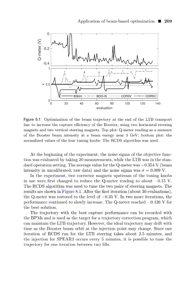
Figure 8.1 Optimization of the beam trajectory at the end of the LTB transport
line to increase the capture efficiency of the Booster, using two horizontal steering
magnets and two vertical steering magnets. Top plot: Q-meter reading as a measure
of the Booster beam intensity at a beam energy near 3 GeV; bottom plot: the
normalized values of the four tuning knobs. The RCDS algorithm was used.
At the beginning of the experiment, the noise sigma of the objective function was evaluated by taking 20 measurements, while the LTB was in the standard operation setting. The average value for the Q-meter was −0.354 V (beam
intensity in uncalibrated, raw data) and the noise sigma was σ = 0.009 V.
In the experiment, two corrector magnets upstream of the tuning knobs
in use were first changed to reduce the Q-meter reading to about −0.15 V.
The RCDS algorithm was used to tune the two pairs of steering magnets. The
results are shown in Figure 8.1. After the first iteration (about 30 evaluations),
the Q-meter was restored to the level of −0.35 V. In two more iterations, the
performance continued to slowly increase. The Q-meter reached −0.426 V for
the best solution.
The trajectory with the best capture performance can be recorded with
the BPMs and is used as the target for a trajectory correction program, which
can maintain the LTB trajectory. However, the ideal trajectory may drift with
time as the Booster beam orbit at the injection point may change. Since one
iteration of RCDS run for the LTB steering takes about 2.5 minutes, and
the injection for SPEAR3 occurs every 5 minutes, it is possible to tune the
trajectory for one iteration between two fills.
-0.4
-0.2
0
Q-meter (V)
0
20
40
60
80
100
120
140
evaluation
0
0.5
1
x
B3trim
BOO-IS
COR3V
COR5V
Figure 8.1 Optimization of the beam trajectory at the end of the LTB transport
line to increase the capture efficiency of the Booster, using two horizontal steering
magnets and two vertical steering magnets. Top plot: Q-meter reading as a measure
of the Booster beam intensity at a beam energy near 3 GeV; bottom plot: the
normalized values of the four tuning knobs. The RCDS algorithm was used.
At the beginning of the experiment, the noise sigma of the objective function was evaluated by taking 20 measurements, while the LTB was in the standard operation setting. The average value for the Q-meter was −0.354 V (beam
intensity in uncalibrated, raw data) and the noise sigma was σ = 0.009 V.
In the experiment, two corrector magnets upstream of the tuning knobs
in use were first changed to reduce the Q-meter reading to about −0.15 V.
The RCDS algorithm was used to tune the two pairs of steering magnets. The
results are shown in Figure 8.1. After the first iteration (about 30 evaluations),
the Q-meter was restored to the level of −0.35 V. In two more iterations, the
performance continued to slowly increase. The Q-meter reached −0.426 V for
the best solution.
The trajectory with the best capture performance can be recorded with
the BPMs and is used as the target for a trajectory correction program, which
can maintain the LTB trajectory. However, the ideal trajectory may drift with
time as the Booster beam orbit at the injection point may change. Since one
iteration of RCDS run for the LTB steering takes about 2.5 minutes, and
the injection for SPEAR3 occurs every 5 minutes, it is possible to tune the
trajectory for one iteration between two fills.