

102 Beam-based Correction and Optimization for Accelerators
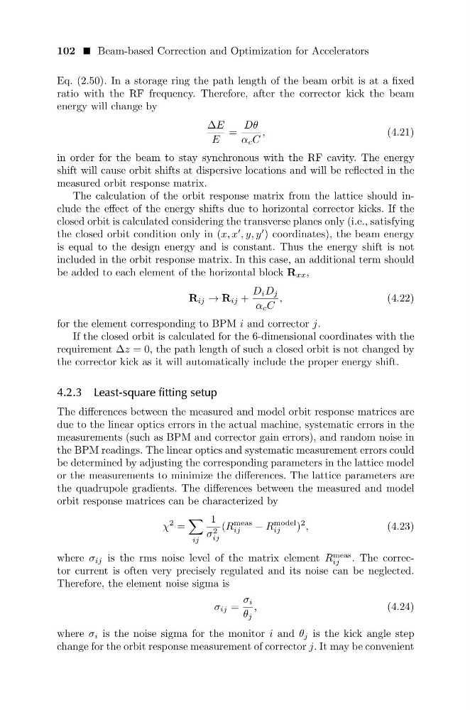
Eq. (2.50). In a storage ring the path length of the beam orbit is at a fixed
ratio with the RF frequency. Therefore, after the corrector kick the beam
energy will change by
∆E
E
=
Dθ
α c C
,
(4.21)
in order for the beam to stay synchronous with the RF cavity. The energy
shift will cause orbit shifts at dispersive locations and will be reflected in the
measured orbit response matrix.
The calculation of the orbit response matrix from the lattice should include the effect of the energy shifts due to horizontal corrector kicks. If the
closed orbit is calculated considering the transverse planes only (i.e., satisfying
the closed orbit condition only in (x, x
, y, y
) coordinates), the beam energy
is equal to the design energy and is constant. Thus the energy shift is not
included in the orbit response matrix. In this case, an additional term should
be added to each element of the horizontal block R xx ,
R ij → R ij +
D i D j
α c C
,
(4.22)
for the element corresponding to BPM i and corrector j.
If the closed orbit is calculated for the 6-dimensional coordinates with the
requirement ∆z = 0, the path length of such a closed orbit is not changed by
the corrector kick as it will automatically include the proper energy shift.
4.2.3 Least-square fitting setup
The differences between the measured and model orbit response matrices are
due to the linear optics errors in the actual machine, systematic errors in the
measurements (such as BPM and corrector gain errors), and random noise in
the BPM readings. The linear optics and systematic measurement errors could
be determined by adjusting the corresponding parameters in the lattice model
or the measurements to minimize the differences. The lattice parameters are
the quadrupole gradients. The differences between the measured and model
orbit response matrices can be characterized by
χ
2 =
ij
1
σ 2
ij
(R
meas
ij
− R
model
ij
)
2 ,
(4.23)
where σ ij is the rms noise level of the matrix element R
meas
ij
. The corrector current is often very precisely regulated and its noise can be neglected.
Therefore, the element noise sigma is
σ ij =
σ i
θ j
,
(4.24)
where σ i is the noise sigma for the monitor i and θ j is the kick angle step
change for the orbit response measurement of corrector j. It may be convenient
Eq. (2.50). In a storage ring the path length of the beam orbit is at a fixed
ratio with the RF frequency. Therefore, after the corrector kick the beam
energy will change by
∆E
E
=
Dθ
α c C
,
(4.21)
in order for the beam to stay synchronous with the RF cavity. The energy
shift will cause orbit shifts at dispersive locations and will be reflected in the
measured orbit response matrix.
The calculation of the orbit response matrix from the lattice should include the effect of the energy shifts due to horizontal corrector kicks. If the
closed orbit is calculated considering the transverse planes only (i.e., satisfying
the closed orbit condition only in (x, x
, y, y
) coordinates), the beam energy
is equal to the design energy and is constant. Thus the energy shift is not
included in the orbit response matrix. In this case, an additional term should
be added to each element of the horizontal block R xx ,
R ij → R ij +
D i D j
α c C
,
(4.22)
for the element corresponding to BPM i and corrector j.
If the closed orbit is calculated for the 6-dimensional coordinates with the
requirement ∆z = 0, the path length of such a closed orbit is not changed by
the corrector kick as it will automatically include the proper energy shift.
4.2.3 Least-square fitting setup
The differences between the measured and model orbit response matrices are
due to the linear optics errors in the actual machine, systematic errors in the
measurements (such as BPM and corrector gain errors), and random noise in
the BPM readings. The linear optics and systematic measurement errors could
be determined by adjusting the corresponding parameters in the lattice model
or the measurements to minimize the differences. The lattice parameters are
the quadrupole gradients. The differences between the measured and model
orbit response matrices can be characterized by
χ
2 =
ij
1
σ 2
ij
(R
meas
ij
− R
model
ij
)
2 ,
(4.23)
where σ ij is the rms noise level of the matrix element R
meas
ij
. The corrector current is often very precisely regulated and its noise can be neglected.
Therefore, the element noise sigma is
σ ij =
σ i
θ j
,
(4.24)
where σ i is the noise sigma for the monitor i and θ j is the kick angle step
change for the orbit response measurement of corrector j. It may be convenient