

88 Beam-based Correction and Optimization for Accelerators
harmonics, n
0
5
10
15
20
|F
n
|
0
0.1
0.2
0.3
0.4
0.5
0.6
before
after
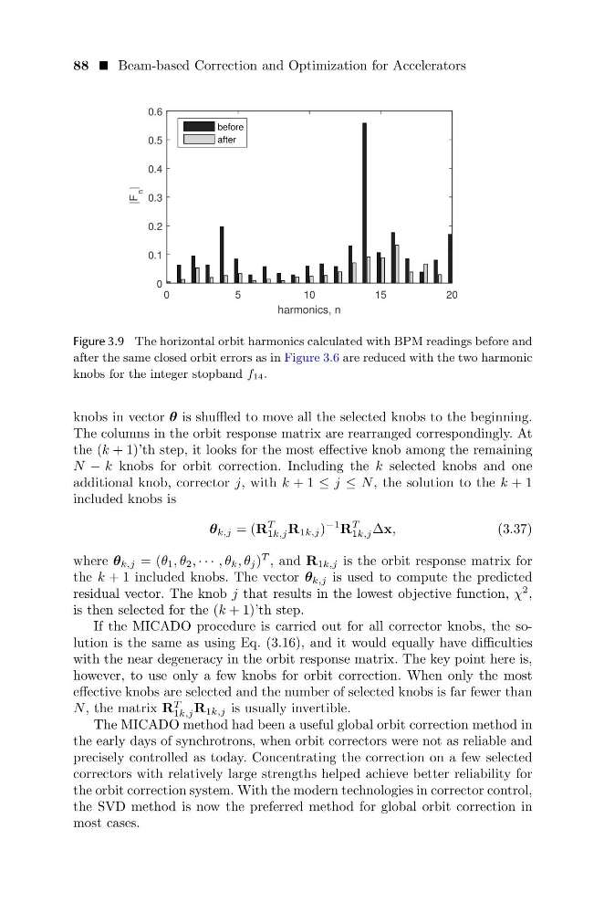
Figure 3.9 The horizontal orbit harmonics calculated with BPM readings before and
after the same closed orbit errors as in Figure 3.6 are reduced with the two harmonic
knobs for the integer stopband f14.
knobs in vector θ is shuffled to move all the selected knobs to the beginning.
The columns in the orbit response matrix are rearranged correspondingly. At
the (k + 1)’th step, it looks for the most effective knob among the remaining
N − k knobs for orbit correction. Including the k selected knobs and one
additional knob, corrector j, with k + 1 ≤ j ≤ N , the solution to the k + 1
included knobs is
θ k,j = (R
T
1k,j R 1k,j )
−1 R
T
1k,j ∆x,
(3.37)
where θ k,j = (θ 1 , θ 2 , · · · , θ k , θ j )
T , and R 1k,j is the orbit response matrix for
the k + 1 included knobs. The vector θ k,j is used to compute the predicted
residual vector. The knob j that results in the lowest objective function, χ
2 ,
is then selected for the (k + 1)’th step.
If the MICADO procedure is carried out for all corrector knobs, the solution is the same as using Eq. (3.16), and it would equally have difficulties
with the near degeneracy in the orbit response matrix. The key point here is,
however, to use only a few knobs for orbit correction. When only the most
effective knobs are selected and the number of selected knobs is far fewer than
N , the matrix R
T
1k,j R 1k,j is usually invertible.
The MICADO method had been a useful global orbit correction method in
the early days of synchrotrons, when orbit correctors were not as reliable and
precisely controlled as today. Concentrating the correction on a few selected
correctors with relatively large strengths helped achieve better reliability for
the orbit correction system. With the modern technologies in corrector control,
the SVD method is now the preferred method for global orbit correction in
most cases.
harmonics, n
0
5
10
15
20
|F
n
|
0
0.1
0.2
0.3
0.4
0.5
0.6
before
after
Figure 3.9 The horizontal orbit harmonics calculated with BPM readings before and
after the same closed orbit errors as in Figure 3.6 are reduced with the two harmonic
knobs for the integer stopband f14.
knobs in vector θ is shuffled to move all the selected knobs to the beginning.
The columns in the orbit response matrix are rearranged correspondingly. At
the (k + 1)’th step, it looks for the most effective knob among the remaining
N − k knobs for orbit correction. Including the k selected knobs and one
additional knob, corrector j, with k + 1 ≤ j ≤ N , the solution to the k + 1
included knobs is
θ k,j = (R
T
1k,j R 1k,j )
−1 R
T
1k,j ∆x,
(3.37)
where θ k,j = (θ 1 , θ 2 , · · · , θ k , θ j )
T , and R 1k,j is the orbit response matrix for
the k + 1 included knobs. The vector θ k,j is used to compute the predicted
residual vector. The knob j that results in the lowest objective function, χ
2 ,
is then selected for the (k + 1)’th step.
If the MICADO procedure is carried out for all corrector knobs, the solution is the same as using Eq. (3.16), and it would equally have difficulties
with the near degeneracy in the orbit response matrix. The key point here is,
however, to use only a few knobs for orbit correction. When only the most
effective knobs are selected and the number of selected knobs is far fewer than
N , the matrix R
T
1k,j R 1k,j is usually invertible.
The MICADO method had been a useful global orbit correction method in
the early days of synchrotrons, when orbit correctors were not as reliable and
precisely controlled as today. Concentrating the correction on a few selected
correctors with relatively large strengths helped achieve better reliability for
the orbit correction system. With the modern technologies in corrector control,
the SVD method is now the preferred method for global orbit correction in
most cases.