

Orbit and trajectory correction 89
3.3.4 Local orbit correction
As we have seen in the example in Section 3.3.2, local orbit bump can be
created with the SVD method by specifying a target orbit that contains orbit
changes only at the desired location(s). The desired orbit bump can involve
multiple locations. For example, to make an angle bump at a location between
two BPMs, the target beam positions on the two BPMs can be shifted in
opposite directions. Even though all BPMs and corrector magnets are used in
the calculation, typically only the correctors in the nearby region are changed.
Changing the weights on the BPMs could help ease up the demand on the
corrector strengths, at the cost of giving up the orbit control at some BPMs.
This method should be able to meet the need of creating local orbit bumps
whenever the orbit response matrix is available.
When an orbit bump is needed at a location without a BPM, the orbit
response matrix can be extended to include an additional row for the target
location. The elements for the row can be calculated with the lattice model.
The SVD method can then be applied to calculate the required corrector
pattern for the local bump.
The traditional method of creating local orbit bump does not rely on
the orbit response matrix or the use of SVD. It is useful to understand the
traditional approach as it would provide helpful insights. The requirement of
a local bump is that the orbit change does not propagate outside of the last
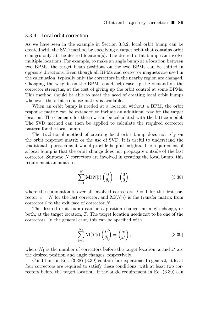
corrector. Suppose N correctors are involved in creating the local bump, this
requirement amounts to
N
i=1
M(N |i)
0
θ i
=
0
0
,
(3.38)
where the summation is over all involved correctors, i = 1 for the first corrector, i = N for the last corrector, and M(N |i) is the transfer matrix from
corrector i to the exit face of corrector N .
The desired orbit bump can be a position change, an angle change, or
both, at the target location, T . The target location needs not to be one of the
correctors. In the general case, this can be specified with
N1
i=1
M(T |i)
0
θ i
=
x
x
,
(3.39)
where N 1 is the number of correctors before the target location, x and x
are
the desired position and angle changes, respectively.
Conditions in Eqs. (3.38)-(3.39) contain four equations. In general, at least
four correctors are required to satisfy these conditions, with at least two correctors before the target location. If the angle requirement in Eq. (3.39) can
3.3.4 Local orbit correction
As we have seen in the example in Section 3.3.2, local orbit bump can be
created with the SVD method by specifying a target orbit that contains orbit
changes only at the desired location(s). The desired orbit bump can involve
multiple locations. For example, to make an angle bump at a location between
two BPMs, the target beam positions on the two BPMs can be shifted in
opposite directions. Even though all BPMs and corrector magnets are used in
the calculation, typically only the correctors in the nearby region are changed.
Changing the weights on the BPMs could help ease up the demand on the
corrector strengths, at the cost of giving up the orbit control at some BPMs.
This method should be able to meet the need of creating local orbit bumps
whenever the orbit response matrix is available.
When an orbit bump is needed at a location without a BPM, the orbit
response matrix can be extended to include an additional row for the target
location. The elements for the row can be calculated with the lattice model.
The SVD method can then be applied to calculate the required corrector
pattern for the local bump.
The traditional method of creating local orbit bump does not rely on
the orbit response matrix or the use of SVD. It is useful to understand the
traditional approach as it would provide helpful insights. The requirement of
a local bump is that the orbit change does not propagate outside of the last
corrector. Suppose N correctors are involved in creating the local bump, this
requirement amounts to
N
i=1
M(N |i)
0
θ i
=
0
0
,
(3.38)
where the summation is over all involved correctors, i = 1 for the first corrector, i = N for the last corrector, and M(N |i) is the transfer matrix from
corrector i to the exit face of corrector N .
The desired orbit bump can be a position change, an angle change, or
both, at the target location, T . The target location needs not to be one of the
correctors. In the general case, this can be specified with
N1
i=1
M(T |i)
0
θ i
=
x
x
,
(3.39)
where N 1 is the number of correctors before the target location, x and x
are
the desired position and angle changes, respectively.
Conditions in Eqs. (3.38)-(3.39) contain four equations. In general, at least
four correctors are required to satisfy these conditions, with at least two correctors before the target location. If the angle requirement in Eq. (3.39) can