

Top Curr Chem (Z) (2018) 376:6
1 3
Raman coherence into a second-order THz-active coherence radiating the signal
field E NL , which is detected by EOS as a function of t. In this case, we have t 1 = τ
and t 2 = t.
These three pulse sequences, as well as the pulse sequence in 2D Raman spectroscopy [64, 65], are complementary to each other. They allow one to study all
THz-active modes, all Raman-active modes, or coupled THz- and Raman-active
modes with flexibility.
2.2.2 Collinear Phase Matching and Differential Chopping Detection
As the wavelength of THz pulses is typically comparable to the spot size of a
focused THz beam, the THz wavevector is not well defined at the focus. The noncollinear FWM method with phase matching satisfied by the BOXCARS geometry,
which has been routinely used in 2D IR and visible spectroscopies, cannot directly
apply to THz fields. However, phase-resolved time-domain THz field detection
and optical birefringence signal detection methods can allow nonlinear THz spectroscopy to be conducted with collinear phase matching, i.e., through wavevectordegenerate FWM.
To separate the nonlinear signals induced by both THz pulses from the signals
induced by each THz pulse individually, a differential chopping detection method
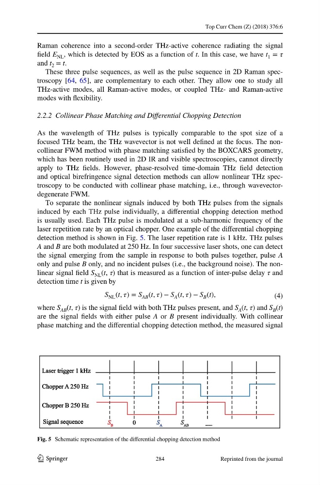
is usually used. Each THz pulse is modulated at a sub-harmonic frequency of the
laser repetition rate by an optical chopper. One example of the differential chopping
detection method is shown in Fig. 5. The laser repetition rate is 1 kHz. THz pulses
A and B are both modulated at 250 Hz. In four successive laser shots, one can detect
the signal emerging from the sample in response to both pulses together, pulse A
only and pulse B only, and no incident pulses (i.e., the background noise). The nonlinear signal field S NL (t, τ) that is measured as a function of inter-pulse delay τ and
detection time t is given by
where S AB (t, τ) is the signal field with both THz pulses present, and S A (t, τ) and S B (t)
are the signal fields with either pulse A or B present individually. With collinear
phase matching and the differential chopping detection method, the measured signal
(4)
S NL (t, ) = S AB (t, ) − S A (t, ) − S B (t),
Fig. 5 Schematic representation of the differential chopping detection method
284
Reprinted from the journal
1 3
Raman coherence into a second-order THz-active coherence radiating the signal
field E NL , which is detected by EOS as a function of t. In this case, we have t 1 = τ
and t 2 = t.
These three pulse sequences, as well as the pulse sequence in 2D Raman spectroscopy [64, 65], are complementary to each other. They allow one to study all
THz-active modes, all Raman-active modes, or coupled THz- and Raman-active
modes with flexibility.
2.2.2 Collinear Phase Matching and Differential Chopping Detection
As the wavelength of THz pulses is typically comparable to the spot size of a
focused THz beam, the THz wavevector is not well defined at the focus. The noncollinear FWM method with phase matching satisfied by the BOXCARS geometry,
which has been routinely used in 2D IR and visible spectroscopies, cannot directly
apply to THz fields. However, phase-resolved time-domain THz field detection
and optical birefringence signal detection methods can allow nonlinear THz spectroscopy to be conducted with collinear phase matching, i.e., through wavevectordegenerate FWM.
To separate the nonlinear signals induced by both THz pulses from the signals
induced by each THz pulse individually, a differential chopping detection method
is usually used. Each THz pulse is modulated at a sub-harmonic frequency of the
laser repetition rate by an optical chopper. One example of the differential chopping
detection method is shown in Fig. 5. The laser repetition rate is 1 kHz. THz pulses
A and B are both modulated at 250 Hz. In four successive laser shots, one can detect
the signal emerging from the sample in response to both pulses together, pulse A
only and pulse B only, and no incident pulses (i.e., the background noise). The nonlinear signal field S NL (t, τ) that is measured as a function of inter-pulse delay τ and
detection time t is given by
where S AB (t, τ) is the signal field with both THz pulses present, and S A (t, τ) and S B (t)
are the signal fields with either pulse A or B present individually. With collinear
phase matching and the differential chopping detection method, the measured signal
(4)
S NL (t, ) = S AB (t, ) − S A (t, ) − S B (t),
Fig. 5 Schematic representation of the differential chopping detection method
284
Reprinted from the journal