

629
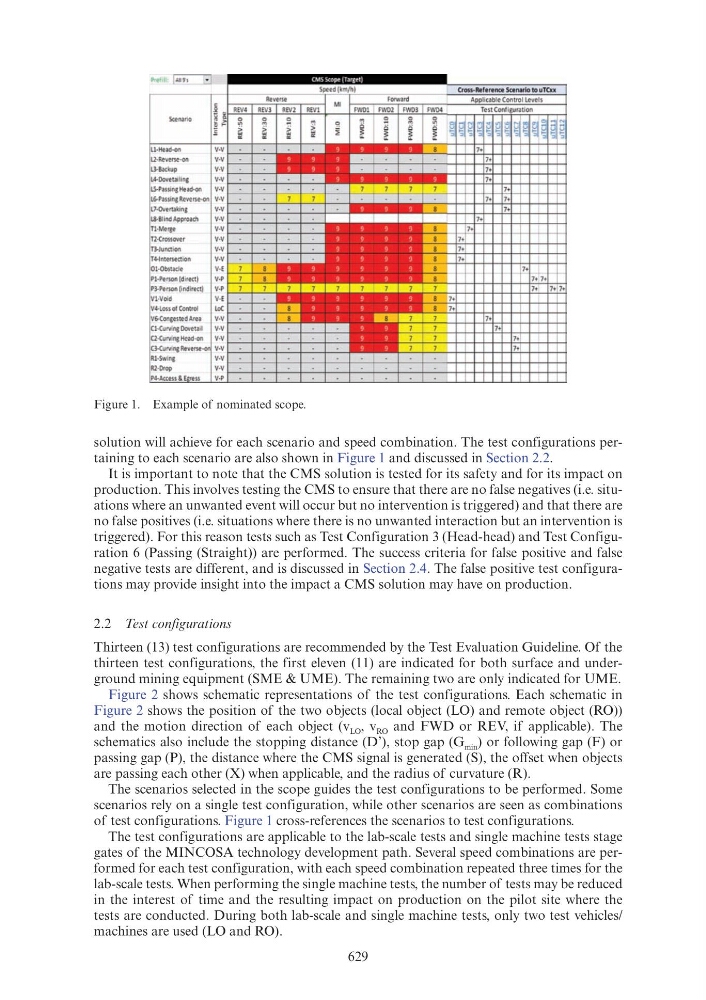
solution will achieve for each scenario and speed combination. The test configurations pertaining to each scenario are also shown in Figure 1 and discussed in Section 2.2.
It is important to note that the CMS solution is tested for its safety and for its impact on
production. This involves testing the CMS to ensure that there are no false negatives (i.e. situations where an unwanted event will occur but no intervention is triggered) and that there are
no false positives (i.e. situations where there is no unwanted interaction but an intervention is
triggered). For this reason tests such as Test Configuration 3 (Head-head) and Test Configuration 6 (Passing (Straight)) are performed. The success criteria for false positive and false
negative tests are different, and is discussed in Section 2.4. The false positive test configurations may provide insight into the impact a CMS solution may have on production.
2.2 Test configurations
Thirteen (13) test configurations are recommended by the Test Evaluation Guideline. Of the
thirteen test configurations, the first eleven (11) are indicated for both surface and underground mining equipment (SME & UME). The remaining two are only indicated for UME.
Figure 2 shows schematic representations of the test configurations. Each schematic in
Figure 2 shows the position of the two objects (local object (LO) and remote object (RO))
and the motion direction of each object (v LO , v RO and FWD or REV, if applicable). The
schematics also include the stopping distance (D’), stop gap (G min ) or following gap (F) or
passing gap (P), the distance where the CMS signal is generated (S), the offset when objects
are passing each other (X) when applicable, and the radius of curvature (R).
The scenarios selected in the scope guides the test configurations to be performed. Some
scenarios rely on a single test configuration, while other scenarios are seen as combinations
of test configurations. Figure 1 cross-references the scenarios to test configurations.
The test configurations are applicable to the lab-scale tests and single machine tests stage
gates of the MINCOSA technology development path. Several speed combinations are performed for each test configuration, with each speed combination repeated three times for the
lab-scale tests. When performing the single machine tests, the number of tests may be reduced
in the interest of time and the resulting impact on production on the pilot site where the
tests are conducted. During both lab-scale and single machine tests, only two test vehicles/
machines are used (LO and RO).
Figure 1. Example of nominated scope.