

630
2.3 Test equipment and site
The lab-scale tests are conducted with two light vehicles. Each vehicle is instrumented with
the following equipment:
• Brake pedal robot and controller (developed at the University of Pretoria)
• Racelogic VBOX 3i Dual Antenna RTK differential GPS with IMU (Racelogic, 2014)
• dSPACE MicroAutoBox II embedded real-time computer (dSPACE GmbH, 2016)
• Complete CMS solution from third party vendor (the solution being tested)
The brake pedal robot consists of a linear actuator and controller that controls the brake
pedal position on each vehicle. When a L9 intervention signal is generated by the CMS, the test
vehicle’s deceleration is controlled by a feedback control system. Deceleration is measured with
the Racelogic VBOX 3i system and controlled by adjusting the brake pedal position. The deceleration is configured before the tests are conducted and is based on recommendation from the
CMS vendor. In the absence of a recommendation from the CMS vendor, a relevant standard is
used to derive the deceleration to be applied during the tests. Standards such as ISO3450:2011
(International Organisation of Standardisation, 2011) and SANS1589-1:2012 (South African
Bureau of Standards., 2012) are then recommended, based on the CMS solution’s intended
application.
The use of a feedback control loop and brake pedal robot to control the deceleration of
the test vehicles results in braking performance that is equivalent to that of a TMM. This is
illustrated in the following equation showing the demand forces acting on a vehicle (Gillespie,
1992):
F
F
F
F
F
ma
demand
F
brakes
F F
drag
F
gradien
F F
t
r
F F olling resistance
x
− F
−
⇒
=
ma x
brakes b b
drag
gradient
r olling resistance
x
b rakes
ma
ma
ma
a
a
x
a
+
+
drag
ma
+
∴ =
a x
+ drag d d
gradient
r olling resistance
a
a
gradient
+
+
a gradient
where F represents a force, m is the mass of the TMM, and a is the deceleration. By controlling a x , the deceleration of the TMM as a system, the impact of friction coefficient
(represented by a brakes , aerodynamic drag (a drag ), gradient (a gradient , and rolling resistance
(a rolling resistance ) are lumped together and taken into account.
The vehicle positions, orientations, speeds and accelerations are measured with the Racelogic VBOX 3i Dual Antenna RTK differential GPS system (Racelogic, 2014). The Racelogic
VBOX 3i system is a differential GPS that provides absolute positional accuracy of ± 2 cm
and speed accuracy of 0.1 km/h at a sampling rate of 100 Hz. A RTK GNSS base station
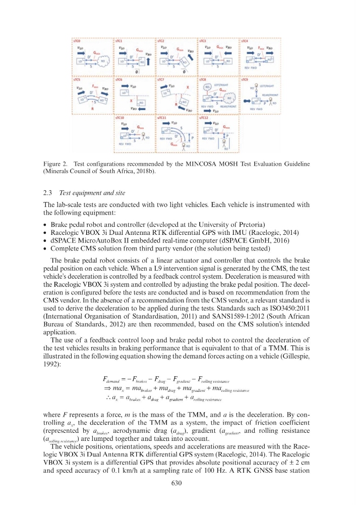
Figure 2. Test configurations recommended by the MINCOSA MOSH Test Evaluation Guideline
(Minerals Council of South Africa, 2018b).
f ;;,o--------------- jf ;Tci--------------- jf ;rei--------------- jf ;;,3--------------- 1[ ;;,4---------------·
:
ll£0
::
Vw
::
Vw
G
::
Vw
Gm.~~ VRo
Vw
Fm~r~ Vtw
' ...:
G_
:: . . .
G~ v,o :: ...:
~ "•o :: ...
...
... 0' \ . . .
~-···Go ll ~~ o·
~'·r;J:l
~"
E)
" l
, ,0
" ~·J;;Gl
~
1~
::
5
::
1 5
::
5
REV FWD S
~------------------;~---------~-------!~-----------~----~~------------------:~------------------: : ;r,s·--------------:: ;r c6·--------------:: ;r,7·--------------1[ ;;,g·--------------:: ;;,g·--------------~
:
f
. . . 11,..,
~ VLQ
X
"
r;;;;'\ LEFT/RIGHT
Q EFT/RGT
: Vw
mlro
VRO
....,
........
"
~
RO h_ l
l H
'
: ~~: . . ~ ~---;----- GS--ci~' 11 ~-~- ~
t REAR/FRONT :
! ~~l!!!.J
X ~
R ~ ::
s ~ :: - ~~RO '
II
VRO . . .
"
...... VRO
:: R~OVL.Q REAR/FRONT ::
REV fWD
L • • -
'1-~~~_,._,._....,._...,_.,...,._.,..,._,._.._.._.._..!1-...-_.._..._..._._.._..._.._..._..._.._.._..._..._..._.._..._...!~.r.I'.I'.I'.I'.I".I".I".JI"..I!'.I".I'.I'.I'.I'.II"I.r!L
: sTC10
:: uTC11
:: uTC12
vw
:: ... vw
:: ... vw
. . .
G~,
: : 0 s ., ~ G~,
~··· Q RO ::
~--1-· : : LD 0 """"f p--·
~ 1\
:: REV FWD 0 " 1 \ p i i REV FWD ~ ·- - ~
~-:~~~-----------il ______ ~~:_:~~~---il ___________ ~~-----: