

622
shearer is cutting near the tailgate (TG) and located between shield numbers 140 and 148 of
152 shields on the face. The inset in Figure 2 provides a detailed view of the flow velocity
distribution around the shearer and near the tailgate. Flow obstructions marked in grey represent the coal face, the shearer body, tailgate drive and shield hydraulic jacks.
Figure 2 illustrates the complexity of air flows in the face area. It clearly shows the turbulences caused by sharp turns and obstacles in the flow path. The reference plane 1.5 m above
the coal floor was chosen arbitrarily. It should be noted that different flow patterns may
occur in other reference planes.
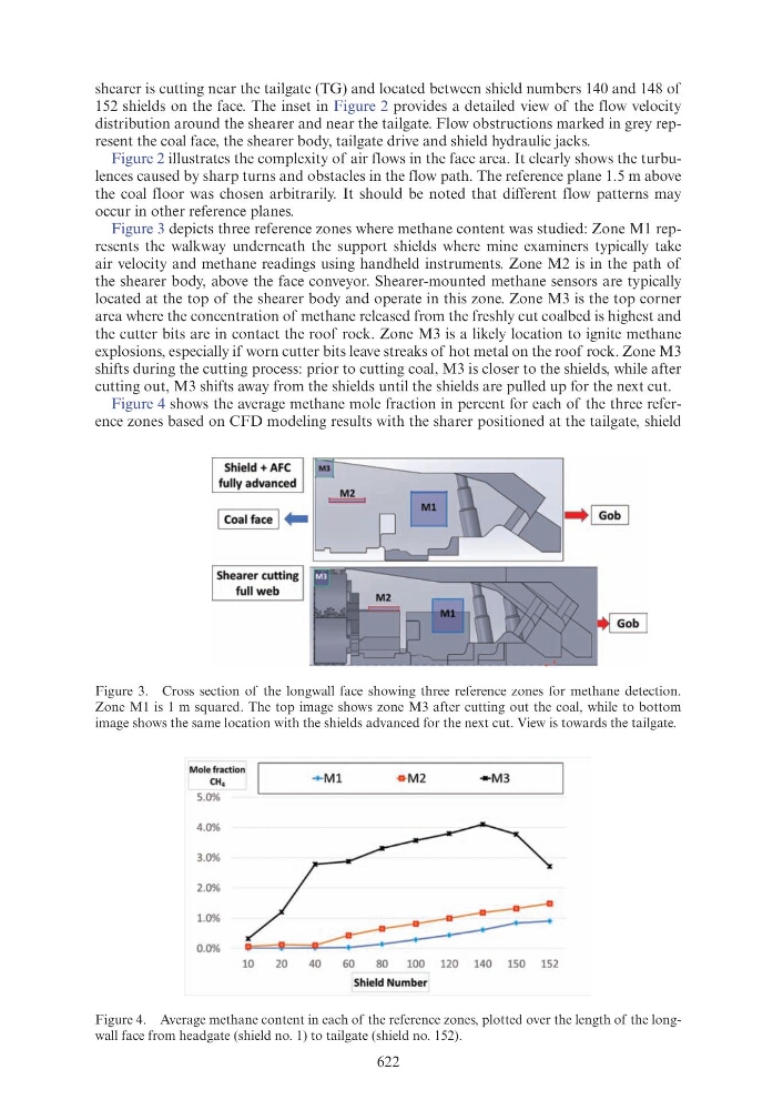
Figure 3 depicts three reference zones where methane content was studied: Zone M1 represents the walkway underneath the support shields where mine examiners typically take
air velocity and methane readings using handheld instruments. Zone M2 is in the path of
the shearer body, above the face conveyor. Shearer-mounted methane sensors are typically
located at the top of the shearer body and operate in this zone. Zone M3 is the top corner
area where the concentration of methane released from the freshly cut coalbed is highest and
the cutter bits are in contact the roof rock. Zone M3 is a likely location to ignite methane
explosions, especially if worn cutter bits leave streaks of hot metal on the roof rock. Zone M3
shifts during the cutting process: prior to cutting coal, M3 is closer to the shields, while after
cutting out, M3 shifts away from the shields until the shields are pulled up for the next cut.
Figure 4 shows the average methane mole fraction in percent for each of the three reference zones based on CFD modeling results with the sharer positioned at the tailgate, shield
Figure 3. Cross section of the longwall face showing three reference zones for methane detection.
Zone M1 is 1 m squared. The top image shows zone M3 after cutting out the coal, while to bottom
image shows the same location with the shields advanced for the next cut. View is towards the tailgate.
Figure 4. Average methane content in each of the reference zones, plotted over the length of the longwall face from headgate (shield no. 1) to tailgate (shield no. 152).
Shield+ AFC
fully advanced
Shearer cutting
full web
Mole fraction
CH4
5.0%
4.0%
3.0%
2.0%
1.0%
0.0%
10
20
+ Ml
40
• M 2
- M3
60
80
100 120 140 150 152
Shie ld Number