

580
Depending on the individual profile requirements of the monitoring, currently two different monitoring concepts (two development stages) can be implemented.
3 DEVELOPMENT STAGE 1: THE SIGFOX SYSTEM
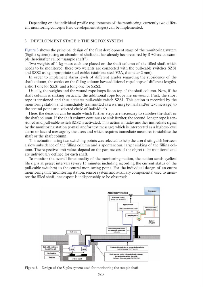
Figure 3 shows the principal design of the first development stage of the monitoring system
(Sigfox system) using an abandoned shaft that has already been restored by RAG as an example (hereinafter called “sample shaft”).
Two weights of 1 kg mass each are placed on the shaft column of the filled shaft which
needs to be monitored; these two weights are connected with the pull-cable switches SZS1
and SZS2 using appropriate steel cables (stainless steel V2A, diameter 2 mm).
In order to implement alarm levels of different grades regarding the subsidence of the
shaft column, the cables on the filling column have additional rope loops of different lengths,
a short one for SZS1 and a long one for SZS2.
Usually, the weights and the wound rope loops lie on top of the shaft column. Now, if the
shaft column is sinking vertically, the additional rope loops are unwound. First, the short
rope is tensioned and thus actuates pull-cable switch SZS1. This action is recorded by the
monitoring station and immediately transmitted as a warning (e-mail and/or text message) to
the central point or a selected circle of individuals.
Here, the decision can be made which further steps are necessary to stabilise the shaft or
the shaft column. If the shaft column continues to sink further, the second, longer rope is tensioned and pull-cable switch SZS2 is activated. This action initiates another immediate signal
by the monitoring station (e-mail and/or text message) which is interpreted as a highest-level
alarm or hazard message by the users and which requires immediate measures to stabilise the
shaft or the shaft column.
This actuation using two switching points was selected to help the user distinguish between
a slow subsidence of the filling column and a spontaneous, larger sinking of the filling column. The respective limit values depend on the parameters of the object to be monitored and
are individually defined for each shaft.
To monitor the overall functionality of the monitoring station, the station sends cyclical
life signs at preset intervals (every 15 minutes including recording the current status of the
pull-cable switches) to the central monitoring point. For the individual design of an entire
monitoring unit (monitoring station, sensor system and auxiliary components) used to monitor the filled shaft, one aspect is indispensably to be observed:
Figure 3. Design of the Sigfox system used for monitoring the sample shaft.