

581
Depending on the shaft type and the conditions inside the shaft and its immediate surroundings, there can be a release of different and in certain cases explosive gas mixtures.
Therefore, all monitoring systems installed of any kind must comply with the requirements
of explosion protection. That means that the electrical and electronic systems in use must
full-fil the requirements of the type of protection Intrinsic Safety according to EN 60079ff.
It needs to be checked in each case whether measures of explosion protection have to be
taken at the shaft to be monitored or not. Thus, the following explanations will point out any
additional components that need to be installed at the specific points that are critical regarding intrinsic safety.
Figure 3 above shows an overview of the installation of a monitoring unit that is used to
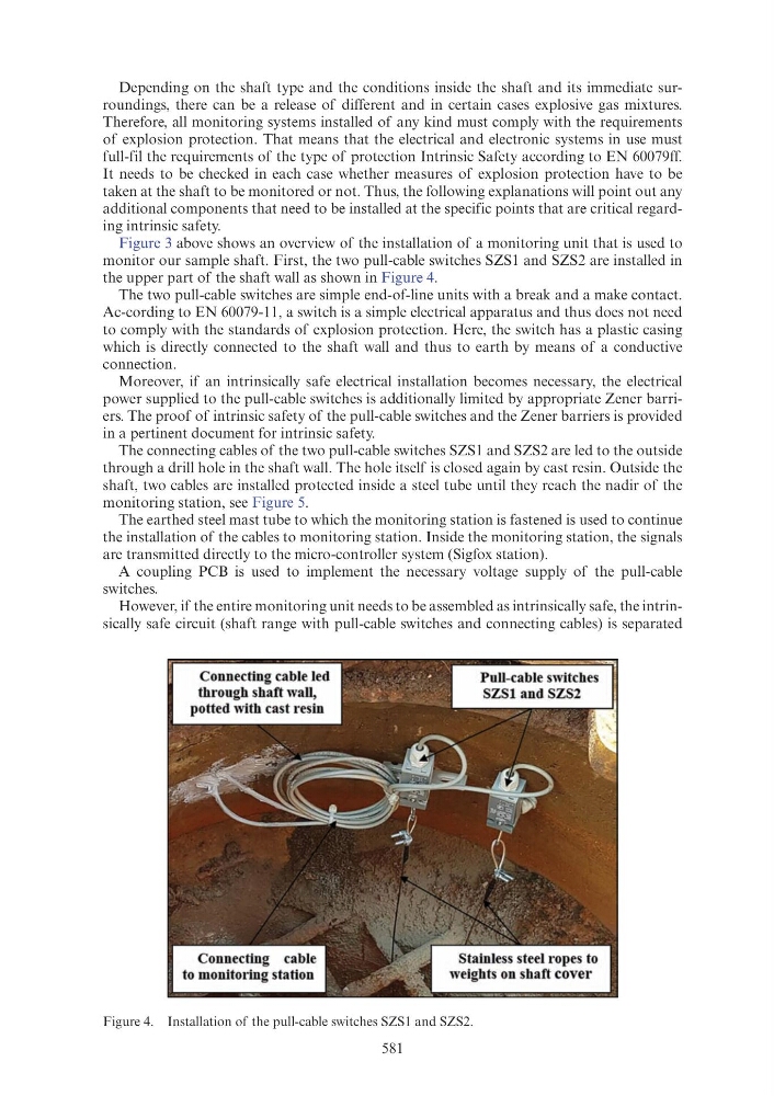
monitor our sample shaft. First, the two pull-cable switches SZS1 and SZS2 are installed in
the upper part of the shaft wall as shown in Figure 4.
The two pull-cable switches are simple end-of-line units with a break and a make contact.
Ac-cording to EN 60079-11, a switch is a simple electrical apparatus and thus does not need
to comply with the standards of explosion protection. Here, the switch has a plastic casing
which is directly connected to the shaft wall and thus to earth by means of a conductive
connection.
Moreover, if an intrinsically safe electrical installation becomes necessary, the electrical
power supplied to the pull-cable switches is additionally limited by appropriate Zener barriers. The proof of intrinsic safety of the pull-cable switches and the Zener barriers is provided
in a pertinent document for intrinsic safety.
The connecting cables of the two pull-cable switches SZS1 and SZS2 are led to the outside
through a drill hole in the shaft wall. The hole itself is closed again by cast resin. Outside the
shaft, two cables are installed protected inside a steel tube until they reach the nadir of the
monitoring station, see Figure 5.
The earthed steel mast tube to which the monitoring station is fastened is used to continue
the installation of the cables to monitoring station. Inside the monitoring station, the signals
are transmitted directly to the micro-controller system (Sigfox station).
A coupling PCB is used to implement the necessary voltage supply of the pull-cable
switches.
However, if the entire monitoring unit needs to be assembled as intrinsically safe, the intrinsically safe circuit (shaft range with pull-cable switches and connecting cables) is separated
Figure 4. Installation of the pull-cable switches SZS1 and SZS2.