

275
3 NUMERICAL EXPERIMENTS
We consider several block models that are openly available. The models are from the MineLib
datasets and provide information not only about block values and coordinates, but also block
sizes and precedence arcs.
Table 1 summarizes the main aspects of these instances in terms of number of blocks,
benches and block sizes, the global and bench face slope angles, and range of variation of the
interramp angles used for different experiments and also information about the ultimate pit
in terms of the final pit values and tonnage.
4 RESULTS AND ANALYSIS
Table 2 shows the main results of this article for the 5 instances described before. For each
instance, we considered a global slope angle and bench face angle, but different values of
interramp angles and a number of benches to control the global angle. We report the differences in terms of tonnage and value after the application of the model and algorithm with
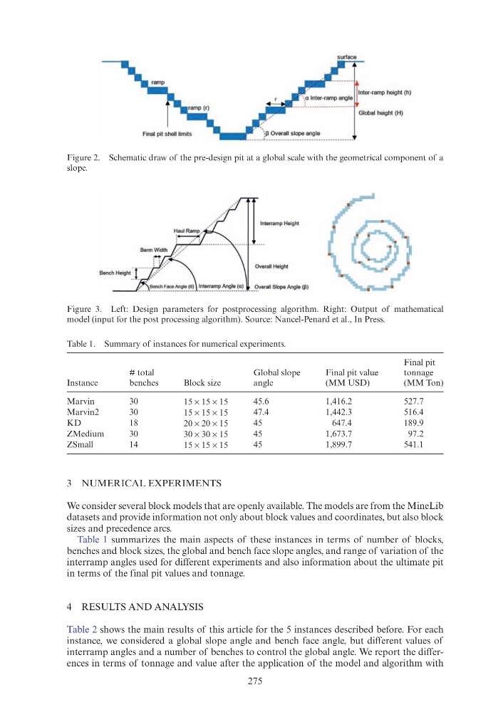
Figure 2. Schematic draw of the pre-design pit at a global scale with the geometrical component of a
slope.
Figure 3. Left: Design parameters for postprocessing algorithm. Right: Output of mathematical
model (input for the post processing algorithm). Source: Nancel-Penard et al., In Press.
Table 1. Summary of instances for numerical experiments.
Instance
# total
benches
Block size
Global slope
angle
Final pit value
(MM USD)
Final pit
tonnage
(MM Ton)
Marvin
30
15 × 15 × 15
45.6
1,416.2
527.7
Marvin2
30
15 × 15 × 15
47.4
1,442.3
516.4
KD
18
20 × 20 × 15
45
647.4
189.9
ZMedium
30
30 × 30 × 15
45
1,673.7
97.2
ZSmall
14
15 × 15 × 15
45
1,899.7
541.1
surface
Final pit shell limits
3 NUMERICAL EXPERIMENTS
We consider several block models that are openly available. The models are from the MineLib
datasets and provide information not only about block values and coordinates, but also block
sizes and precedence arcs.
Table 1 summarizes the main aspects of these instances in terms of number of blocks,
benches and block sizes, the global and bench face slope angles, and range of variation of the
interramp angles used for different experiments and also information about the ultimate pit
in terms of the final pit values and tonnage.
4 RESULTS AND ANALYSIS
Table 2 shows the main results of this article for the 5 instances described before. For each
instance, we considered a global slope angle and bench face angle, but different values of
interramp angles and a number of benches to control the global angle. We report the differences in terms of tonnage and value after the application of the model and algorithm with
Figure 2. Schematic draw of the pre-design pit at a global scale with the geometrical component of a
slope.
Figure 3. Left: Design parameters for postprocessing algorithm. Right: Output of mathematical
model (input for the post processing algorithm). Source: Nancel-Penard et al., In Press.
Table 1. Summary of instances for numerical experiments.
Instance
# total
benches
Block size
Global slope
angle
Final pit value
(MM USD)
Final pit
tonnage
(MM Ton)
Marvin
30
15 × 15 × 15
45.6
1,416.2
527.7
Marvin2
30
15 × 15 × 15
47.4
1,442.3
516.4
KD
18
20 × 20 × 15
45
647.4
189.9
ZMedium
30
30 × 30 × 15
45
1,673.7
97.2
ZSmall
14
15 × 15 × 15
45
1,899.7
541.1
surface
Final pit shell limits