

180
Strain-Engineered MOSFETs
time measurements, the positions of the traps are also determined using
Equation (6.36). The fast-varying RTN is modeled as a four-level RTN originating from two traps, and the trap depths are calculated as 1.374 and 14.5 Å
inside the oxide. The second trap is clearly a slow-varying trap and is located
deeper in the oxide layer.
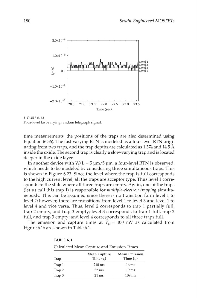
In another device with W/L = 5 μm/5 μm, a four-level RTN is observed,
which needs to be modeled by considering three simultaneous traps. This
is shown in Figure 6.23. Since the level where the trap is full corresponds
to the high current level, all the traps are acceptor type. Thus level 1 corresponds to the state where all three traps are empty. Again, one of the traps
(let us call this trap 1) is responsible for multiple-electron trapping simultaneously. This can be assumed since there is no transition form level 1 to
level 2; however, there are transitions from level 1 to level 3 and level 1 to
level 4 and vice versa. Thus, level 2 corresponds to trap 1 partially full,
trap 2 empty, and trap 3 empty; level 3 corresponds to trap 1 full, trap 2
full, and trap 3 empty; and level 4 corresponds to all three traps full.
The emission and capture times at V gs = 100 mV as calculated from
Figure 6.16 are shown in Table 6.1.
20.5
–2.0×10
–9
–1.0×10
–9
1.0×10
–9
2.0×10
–9
0.0
Level 1
Level 2
Level 3
Level 4
I
d (A)
21.0 21.5 22.0
Time (sec)
22.5 23.0 23.5
FIGURE 6.23
Four-level fast-varying random telegraph signal.
TABLE 6.1
Calculated Mean Capture and Emission Times
Trap
Mean Capture
Time (τ c )
Mean Emission
Time (τ e )
Trap 1
210 ms
16 ms
Trap 2
52 ms
19 ms
Trap 3
21 ms
109 ms
Strain-Engineered MOSFETs
time measurements, the positions of the traps are also determined using
Equation (6.36). The fast-varying RTN is modeled as a four-level RTN originating from two traps, and the trap depths are calculated as 1.374 and 14.5 Å
inside the oxide. The second trap is clearly a slow-varying trap and is located
deeper in the oxide layer.
In another device with W/L = 5 μm/5 μm, a four-level RTN is observed,
which needs to be modeled by considering three simultaneous traps. This
is shown in Figure 6.23. Since the level where the trap is full corresponds
to the high current level, all the traps are acceptor type. Thus level 1 corresponds to the state where all three traps are empty. Again, one of the traps
(let us call this trap 1) is responsible for multiple-electron trapping simultaneously. This can be assumed since there is no transition form level 1 to
level 2; however, there are transitions from level 1 to level 3 and level 1 to
level 4 and vice versa. Thus, level 2 corresponds to trap 1 partially full,
trap 2 empty, and trap 3 empty; level 3 corresponds to trap 1 full, trap 2
full, and trap 3 empty; and level 4 corresponds to all three traps full.
The emission and capture times at V gs = 100 mV as calculated from
Figure 6.16 are shown in Table 6.1.
20.5
–2.0×10
–9
–1.0×10
–9
1.0×10
–9
2.0×10
–9
0.0
Level 1
Level 2
Level 3
Level 4
I
d (A)
21.0 21.5 22.0
Time (sec)
22.5 23.0 23.5
FIGURE 6.23
Four-level fast-varying random telegraph signal.
TABLE 6.1
Calculated Mean Capture and Emission Times
Trap
Mean Capture
Time (τ c )
Mean Emission
Time (τ e )
Trap 1
210 ms
16 ms
Trap 2
52 ms
19 ms
Trap 3
21 ms
109 ms