

169
Noise in Strain-Engineered Devices
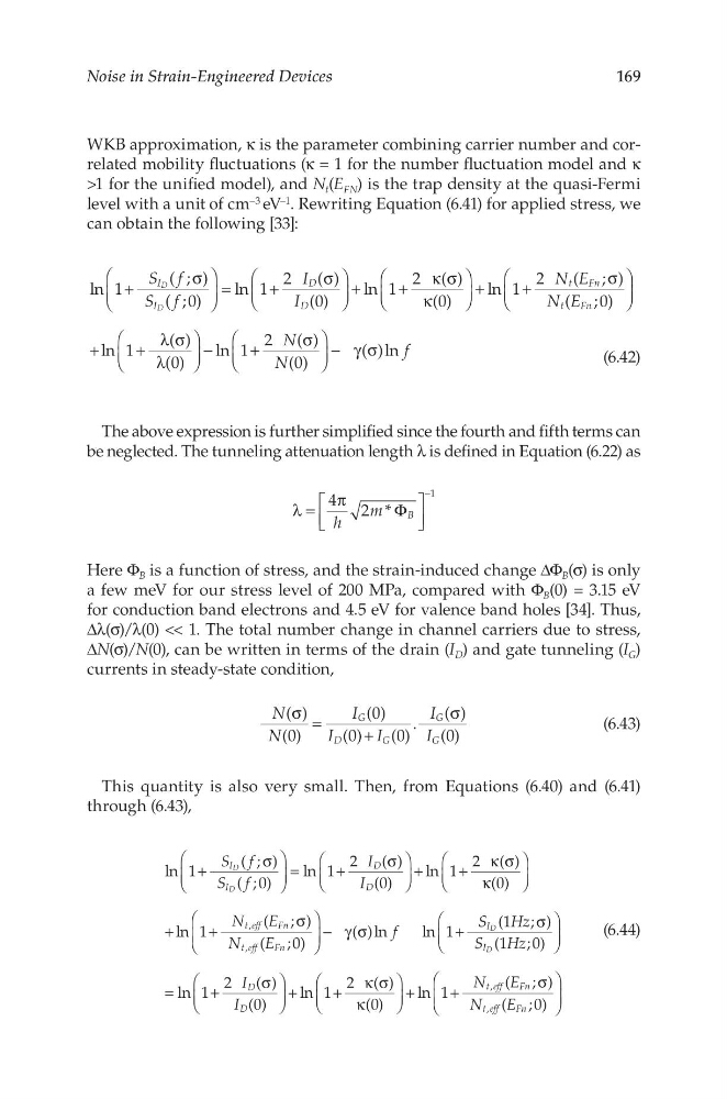
WKB approximation, κ is the parameter combining carrier number and correlated mobility fluctuations (κ = 1 for the number fluctuation model and κ
>1 for the unified model), and N t (E FN ) is the trap density at the quasi-Fermi
level with a unit of cm –3 eV –1 . Rewriting Equation (6.41) for applied stress, we
can obtain the following [33]:
S f
S f
I
I
N E
N E
N
N
f
ln 1
( ; )
( ;0)
ln 1
2
( )
(0)
ln 1
2 ( )
(0)
ln 1
2
( ; )
( ;0)
ln 1
( )
(0)
ln 1
2 ( )
(0)
( )ln
I
I
D
D
t
Fn
t
Fn
D
D
+
σ
=
+
σ
+
+
κ σ
κ
+
+
σ
+
+
λ σ
λ
−
+
σ
− γ σ
(6.42)
The above expression is further simplified since the fourth and fifth terms can
be neglected. The tunneling attenuation length λ is defined in Equation (6.22) as
h
m
4 2 * B
1
λ =
π
Φ
−
Here Φ B is a function of stress, and the strain-induced change ΔΦ B (σ) is only
a few meV for our stress level of 200 MPa, compared with Φ B (0) = 3.15 eV
for conduction band electrons and 4.5 eV for valence band holes [34]. Thus,
Δλ(σ)/λ(0) << 1. The total number change in channel carriers due to stress,
ΔN(σ)/N(0), can be written in terms of the drain (I D ) and gate tunneling (I G )
currents in steady-state condition,
N
N
I
I
I
I
I
( )
(0)
(0)
(0)
(0)
.
( )
(0)
G
D
G
G
G
σ =
+
σ
(6.43)
This quantity is also very small. Then, from Equations (6.40) and (6.41)
through (6.43),
S f
S f
I
I
N
E
N
E
f
S
Hz
S
Hz
I
I
N
E
N
E
ln 1
( ; )
( ;0)
ln 1
2
( )
(0)
ln 1
2 ( )
(0)
ln 1
( ; )
( ;0)
( )ln
ln 1
(1 ; )
(1 ; 0)
ln 1
2
( )
(0)
ln 1
2 ( )
(0)
ln 1
( ; )
( ;0)
I
I
D
D
t eff
Fn
t eff
Fn
I
I
D
D
t eff
Fn
t eff
Fn
,
,
,
,
D
D
D
D
+
σ
=
+
σ
+
+
κ σ
κ
+
+
σ
− γ σ
+
σ
=
+
σ
+
+
κ σ
κ
+
+
σ
(6.44)
Noise in Strain-Engineered Devices
WKB approximation, κ is the parameter combining carrier number and correlated mobility fluctuations (κ = 1 for the number fluctuation model and κ
>1 for the unified model), and N t (E FN ) is the trap density at the quasi-Fermi
level with a unit of cm –3 eV –1 . Rewriting Equation (6.41) for applied stress, we
can obtain the following [33]:
S f
S f
I
I
N E
N E
N
N
f
ln 1
( ; )
( ;0)
ln 1
2
( )
(0)
ln 1
2 ( )
(0)
ln 1
2
( ; )
( ;0)
ln 1
( )
(0)
ln 1
2 ( )
(0)
( )ln
I
I
D
D
t
Fn
t
Fn
D
D
+
σ
=
+
σ
+
+
κ σ
κ
+
+
σ
+
+
λ σ
λ
−
+
σ
− γ σ
(6.42)
The above expression is further simplified since the fourth and fifth terms can
be neglected. The tunneling attenuation length λ is defined in Equation (6.22) as
h
m
4 2 * B
1
λ =
π
Φ
−
Here Φ B is a function of stress, and the strain-induced change ΔΦ B (σ) is only
a few meV for our stress level of 200 MPa, compared with Φ B (0) = 3.15 eV
for conduction band electrons and 4.5 eV for valence band holes [34]. Thus,
Δλ(σ)/λ(0) << 1. The total number change in channel carriers due to stress,
ΔN(σ)/N(0), can be written in terms of the drain (I D ) and gate tunneling (I G )
currents in steady-state condition,
N
N
I
I
I
I
I
( )
(0)
(0)
(0)
(0)
.
( )
(0)
G
D
G
G
G
σ =
+
σ
(6.43)
This quantity is also very small. Then, from Equations (6.40) and (6.41)
through (6.43),
S f
S f
I
I
N
E
N
E
f
S
Hz
S
Hz
I
I
N
E
N
E
ln 1
( ; )
( ;0)
ln 1
2
( )
(0)
ln 1
2 ( )
(0)
ln 1
( ; )
( ;0)
( )ln
ln 1
(1 ; )
(1 ; 0)
ln 1
2
( )
(0)
ln 1
2 ( )
(0)
ln 1
( ; )
( ;0)
I
I
D
D
t eff
Fn
t eff
Fn
I
I
D
D
t eff
Fn
t eff
Fn
,
,
,
,
D
D
D
D
+
σ
=
+
σ
+
+
κ σ
κ
+
+
σ
− γ σ
+
σ
=
+
σ
+
+
κ σ
κ
+
+
σ
(6.44)