

143
6
Noise in Strain-Engineered Devices
C. Mukherjee
Indian Institute of Technology, Kharagpur
The planar device architecture of conventional metal-oxide-semiconductor
field-effect transistors (MOSFETs) is limited to scaling beyond 15 nm
gate length due to transistor switching criteria. Complementary metaloxide-semiconductor (CMOS) technology has been scaled during the past 30
years with a drive to continuously increase the density of devices on a chip
and increase the switching performance of transistors, the major components
of electronic circuits. Toward the end of the ITRS road map [1], in which the
channel length is predicted to be aggressively scaled, careful device design
consideration is required due to trade-offs between device current drive,
short-channel effects, and power consumption. The on-state current (I on ) of a
MOSFET is represented by
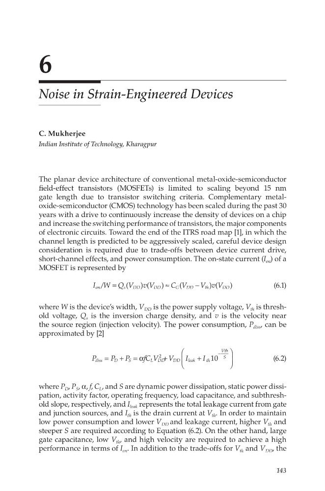
I W Q V v V
C V
V v V
/
(
) (
)
(
) (
)
on
s
DD
D D
G
DD
th
DD
=
≈
−
(6.1)
where W is the device’s width, V DD is the power supply voltage, V th is threshold voltage, Q s is the inversion charge density, and v is the velocity near
the source region (injection velocity). The power consumption, P diss , can be
approximated by [2]
P
P P
fC V V
I
I 10
diss
D
S
L DD
D D
leak
t h
Vth
S
2
= + = α
+
+
−
(6.2)
where P D , P S , α, f, C L , and S are dynamic power dissipation, static power dissipation, activity factor, operating frequency, load capacitance, and subthreshold slope, respectively, and I leak represents the total leakage current from gate
and junction sources, and I th is the drain current at V th . In order to maintain
low power consumption and lower V DD and leakage current, higher V th and
steeper S are required according to Equation (6.2). On the other hand, large
gate capacitance, low V th , and high velocity are required to achieve a high
performance in terms of I on . In addition to the trade-offs for V th and V DD , the
6
Noise in Strain-Engineered Devices
C. Mukherjee
Indian Institute of Technology, Kharagpur
The planar device architecture of conventional metal-oxide-semiconductor
field-effect transistors (MOSFETs) is limited to scaling beyond 15 nm
gate length due to transistor switching criteria. Complementary metaloxide-semiconductor (CMOS) technology has been scaled during the past 30
years with a drive to continuously increase the density of devices on a chip
and increase the switching performance of transistors, the major components
of electronic circuits. Toward the end of the ITRS road map [1], in which the
channel length is predicted to be aggressively scaled, careful device design
consideration is required due to trade-offs between device current drive,
short-channel effects, and power consumption. The on-state current (I on ) of a
MOSFET is represented by
I W Q V v V
C V
V v V
/
(
) (
)
(
) (
)
on
s
DD
D D
G
DD
th
DD
=
≈
−
(6.1)
where W is the device’s width, V DD is the power supply voltage, V th is threshold voltage, Q s is the inversion charge density, and v is the velocity near
the source region (injection velocity). The power consumption, P diss , can be
approximated by [2]
P
P P
fC V V
I
I 10
diss
D
S
L DD
D D
leak
t h
Vth
S
2
= + = α
+
+
−
(6.2)
where P D , P S , α, f, C L , and S are dynamic power dissipation, static power dissipation, activity factor, operating frequency, load capacitance, and subthreshold slope, respectively, and I leak represents the total leakage current from gate
and junction sources, and I th is the drain current at V th . In order to maintain
low power consumption and lower V DD and leakage current, higher V th and
steeper S are required according to Equation (6.2). On the other hand, large
gate capacitance, low V th , and high velocity are required to achieve a high
performance in terms of I on . In addition to the trade-offs for V th and V DD , the