

90
Strain-Engineered MOSFETs
The shear stress can be further decomposed into two orthogonal force components giving rise to three total stress components acting on each plane.
Figure 4.1 shows the normal and shear stresses in X, Y, and Z directions acting on different planes of the cube. The first subscript identifies the face on
which the stress is acting, and the second subscript identifies the direction.
The σ ij components are the normal stresses, while the σ ij components are the
shear stresses.
4.2 Stress–Strain Relationships
Generally, the stress tensor σ is symmetric 3 × 3 matrices. Therefore, it only
has six independent components. With the index transformation rule, it can
be written in a six-component vector notation, σ 11 → σ 1 , σ 22 → σ 2 , σ 33 → σ 3 ,
σ 23 → (σ 4 )/2, σ 13 → (σ 5 )/2, σ 12 → (σ 6 )/2, that simplifies tensor expressions. For
example, to compute the strain tensor (which is needed for the deformation
potential model development), the generalised Hooke’s law for anisotropic
materials is applied as
1
6
S
ij
ij j
j
∑
ε =
σ
=
(4.2)
where S ij is the elasticity modulus. In crystals with cubic symmetry such as
silicon, the number of independent coefficients of the elasticity tensor (as
other material property tensors) reduces to three by rotating the coordinate
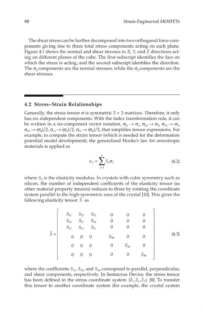
system parallel to the high-symmetric axes of the crystal [10]. This gives the
following elasticity tensor S as
0
0
0
0
0
0
0
0
0
0 0 0
0
0
0 0 0
0
0
0 0 0
0
0
11
12
12
12
11
12
12
12
11
44
44
44
S
S
S
S
S
S
S
S
S
S
S
S
S
=
(4.3)
where the coefficients S 11 , S 12 , and S 44 correspond to parallel, perpendicular,
and shear components, respectively. In Sentaurus Device, the stress tensor
has been defined in the stress coordinate system ( , , )
1 2
3
e e e
[8]. To transfer
this tensor to another coordinate system (for example, the crystal system
Strain-Engineered MOSFETs
The shear stress can be further decomposed into two orthogonal force components giving rise to three total stress components acting on each plane.
Figure 4.1 shows the normal and shear stresses in X, Y, and Z directions acting on different planes of the cube. The first subscript identifies the face on
which the stress is acting, and the second subscript identifies the direction.
The σ ij components are the normal stresses, while the σ ij components are the
shear stresses.
4.2 Stress–Strain Relationships
Generally, the stress tensor σ is symmetric 3 × 3 matrices. Therefore, it only
has six independent components. With the index transformation rule, it can
be written in a six-component vector notation, σ 11 → σ 1 , σ 22 → σ 2 , σ 33 → σ 3 ,
σ 23 → (σ 4 )/2, σ 13 → (σ 5 )/2, σ 12 → (σ 6 )/2, that simplifies tensor expressions. For
example, to compute the strain tensor (which is needed for the deformation
potential model development), the generalised Hooke’s law for anisotropic
materials is applied as
1
6
S
ij
ij j
j
∑
ε =
σ
=
(4.2)
where S ij is the elasticity modulus. In crystals with cubic symmetry such as
silicon, the number of independent coefficients of the elasticity tensor (as
other material property tensors) reduces to three by rotating the coordinate
system parallel to the high-symmetric axes of the crystal [10]. This gives the
following elasticity tensor S as
0
0
0
0
0
0
0
0
0
0 0 0
0
0
0 0 0
0
0
0 0 0
0
0
11
12
12
12
11
12
12
12
11
44
44
44
S
S
S
S
S
S
S
S
S
S
S
S
S
=
(4.3)
where the coefficients S 11 , S 12 , and S 44 correspond to parallel, perpendicular,
and shear components, respectively. In Sentaurus Device, the stress tensor
has been defined in the stress coordinate system ( , , )
1 2
3
e e e
[8]. To transfer
this tensor to another coordinate system (for example, the crystal system