

The HTS effluent is cooled further. In pressure swing adsorption (PSA)-based
plants, the effluent is normally cooled all the way to near-ambient conditions
without further shift. In plants employing a wet chemical purification system and
in a few PSA plants, there is a low-temperature shift (LTS) reactor to make
additional hydrogen and eliminate more CO. Some plants use medium temperature
shift (MTS) reactors, but these are less common.
The LTS reactor normally uses a copper-based catalyst to reduce the residual CO to
less than $0.5 v% (can be as low as 0.1 %). This type of catalyst is not robust, so
activation and management of the LTS catalyst requires special procedures. A LTS
reactor tends to make methanol and ammonia, which will contribute to emissions later.
This issue is exacerbated by very low steam/carbon ratios. Specific, low-methanol
catalysts are available to limit these side reactions. For a unit with only HTS, the
addition of LTS can increase hydrogen production 5–10 %, provided the purification
system can handle the extra load. Purification may need to be debottlenecked.
In the final steps of shift effluent cooling, we condense and recover the unreacted
steam (shift condensate) for reuse. The relatively dry raw hydrogen is then sent to
final purification.
Shift condensate will be saturated with CO 2 and is quite corrosive. It is handled in
stainless steel equipment. Direct reuse of the condensate with the dissolved CO 2
would cause high corrosion rates in the boiler system and introduce excessive amounts
of CO 2 into the steam from the hydrogen plant – causing high corrosion rates in
condensate systems throughout the refinery. Before reuse, the shift condensate must be
“degassed” by steam stripping to remove the CO 2 . This can be done separately in a
dedicated stripper or degasifier or combined with deaeration of incoming boiler
feedwater (BFW). Combining degassing with deaeration is generally less effective.
Because the shift condensate also contains methanol and other trace organic
oxygenates plus trace ammonia, disposal of the stripper or degasifier off-gas must
be considered. Environmental regulations limit the options in many areas. If a unit
only has HTS, degasifier off-gas can often go to atmosphere. In other cases, the
degasifier or deaerator off-gas can be routed to the reforming furnace firebox. Some
units use high-pressure steam strippers to remove the dissolved gases, with the
stripper off-gases routed back to feed as part of the process steam.
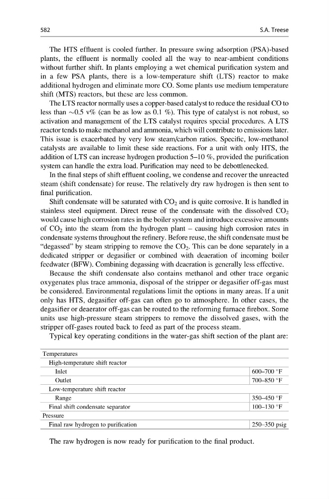
Typical key operating conditions in the water-gas shift section of the plant are:
Temperatures
High-temperature shift reactor
Inlet
600–700
F
Outlet
700–850
F
Low-temperature shift reactor
Range
350–450
F
Final shift condensate separator
100–130
F
Pressure
Final raw hydrogen to purification
250–350 psig
The raw hydrogen is now ready for purification to the final product.
582
S.A. Treese