

Tube pressure drop
15–40 psi
Catalyst volume/GHSV
By designer
Firebox-side conditions
Firebox temperature (firing level)
2,000–2,200
F
Draft at burners
0.5–1.5 “H 2 O
Flue gas exiting firebox (bridgewall)
1,750–1,850
F
Water-Gas Shift
The outlet from the reforming furnace consists of hydrogen, CO, CO 2 , residual
CH 4 , a lot of steam, plus any inerts. These products are all at or close to equilibrium
at the process outlet temperature from the furnace, usually in the 1,350–1,740
F
range. At these temperatures, there will still be 30–70 % of the carbon present as
CO. This CO can be “shifted” to CO 2 with incremental production of hydrogen at
lower temperatures using the water-gas shift reaction:
CO þ H 2 O ! CO 2 þ H 2 þ Heat
(17)
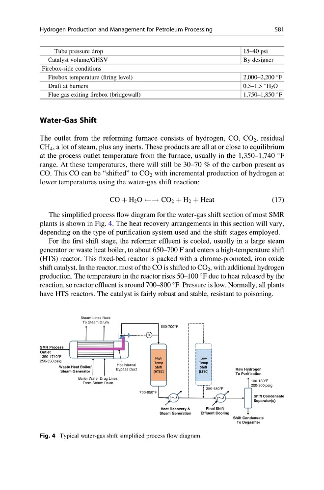
The simplified process flow diagram for the water-gas shift section of most SMR
plants is shown in Fig. 4. The heat recovery arrangements in this section will vary,
depending on the type of purification system used and the shift stages employed.
For the first shift stage, the reformer effluent is cooled, usually in a large steam
generator or waste heat boiler, to about 650–700 F and enters a high-temperature shift
(HTS) reactor. This fixed-bed reactor is packed with a chrome-promoted, iron oxide
shift catalyst. In the reactor, most of the CO is shifted to CO 2 , with additional hydrogen
production. The temperature in the reactor rises 50–100
F due to heat released by the
reaction, so reactor effluent is around 700–800
F. Pressure is low. Normally, all plants
have HTS reactors. The catalyst is fairly robust and stable, resistant to poisoning.
600-700°F
SMR Process
Outlet
1350-1740°F
250-350 psig
Waste Heat Boiler/
Steam Generator
Hot Internal
Bypass Duct
100-130°F
200-300 psig
350-450°F
700-850°F
Shift Condensate
Separator(s)
Final Shift
Effluent Cooling
Raw Hydrogen
To Purification
Shift Condensate
To Degasifier
Boiler Water Drag Lines
From Steam Drum
Steam Lines Back
To Steam Drum
Heat Recovery &
Steam Generation
High
Temp
Shift
(HTSC)
Low
Temp
Shift
(LTSC)
TC
Fig. 4 Typical water-gas shift simplified process flow diagram
Hydrogen Production and Management for Petroleum Processing
581