

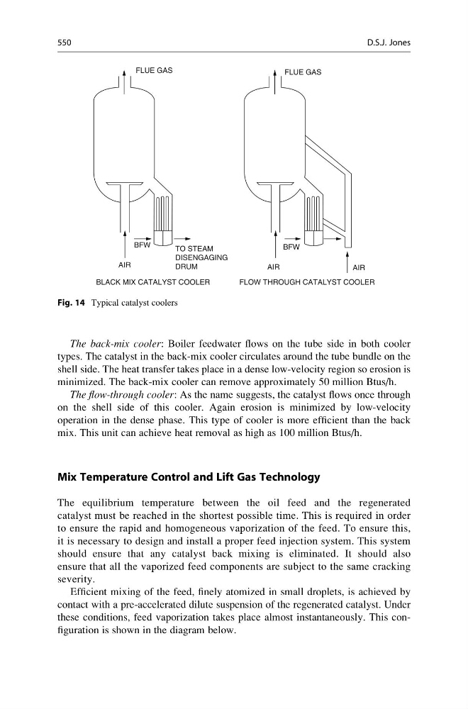
The back-mix cooler: Boiler feedwater flows on the tube side in both cooler
types. The catalyst in the back-mix cooler circulates around the tube bundle on the
shell side. The heat transfer takes place in a dense low-velocity region so erosion is
minimized. The back-mix cooler can remove approximately 50 million Btus/h.
The flow-through cooler: As the name suggests, the catalyst flows once through
on the shell side of this cooler. Again erosion is minimized by low-velocity
operation in the dense phase. This type of cooler is more efficient than the back
mix. This unit can achieve heat removal as high as 100 million Btus/h.
Mix Temperature Control and Lift Gas Technology
The equilibrium temperature between the oil feed and the regenerated
catalyst must be reached in the shortest possible time. This is required in order
to ensure the rapid and homogeneous vaporization of the feed. To ensure this,
it is necessary to design and install a proper feed injection system. This system
should ensure that any catalyst back mixing is eliminated. It should also
ensure that all the vaporized feed components are subject to the same cracking
severity.
Efficient mixing of the feed, finely atomized in small droplets, is achieved by
contact with a pre-accelerated dilute suspension of the regenerated catalyst. Under
these conditions, feed vaporization takes place almost instantaneously. This configuration is shown in the diagram below.
TO STEAM
DISENGAGING
DRUM
BFW
BFW
FLUE GAS
FLUE GAS
AIR
AIR
AIR
BLACK MIX CATALYST COOLER
FLOW THROUGH CATALYST COOLER
Fig. 14 Typical catalyst coolers
550
D.S.J. Jones
types. The catalyst in the back-mix cooler circulates around the tube bundle on the
shell side. The heat transfer takes place in a dense low-velocity region so erosion is
minimized. The back-mix cooler can remove approximately 50 million Btus/h.
The flow-through cooler: As the name suggests, the catalyst flows once through
on the shell side of this cooler. Again erosion is minimized by low-velocity
operation in the dense phase. This type of cooler is more efficient than the back
mix. This unit can achieve heat removal as high as 100 million Btus/h.
Mix Temperature Control and Lift Gas Technology
The equilibrium temperature between the oil feed and the regenerated
catalyst must be reached in the shortest possible time. This is required in order
to ensure the rapid and homogeneous vaporization of the feed. To ensure this,
it is necessary to design and install a proper feed injection system. This system
should ensure that any catalyst back mixing is eliminated. It should also
ensure that all the vaporized feed components are subject to the same cracking
severity.
Efficient mixing of the feed, finely atomized in small droplets, is achieved by
contact with a pre-accelerated dilute suspension of the regenerated catalyst. Under
these conditions, feed vaporization takes place almost instantaneously. This configuration is shown in the diagram below.
TO STEAM
DISENGAGING
DRUM
BFW
BFW
FLUE GAS
FLUE GAS
AIR
AIR
AIR
BLACK MIX CATALYST COOLER
FLOW THROUGH CATALYST COOLER
Fig. 14 Typical catalyst coolers
550
D.S.J. Jones