

refractory lined and there is no temperature constraint. The catalyst is allowed to
come to equilibrium. Even at high regenerator temperatures, under these conditions
lower catalyst deactivation is experienced. The two-stage regeneration technique
leads to a better catalyst regeneration as well as a lower catalyst consumption.
Typically, the clean catalyst contains less than 0.05 wt% carbon. This is achieved
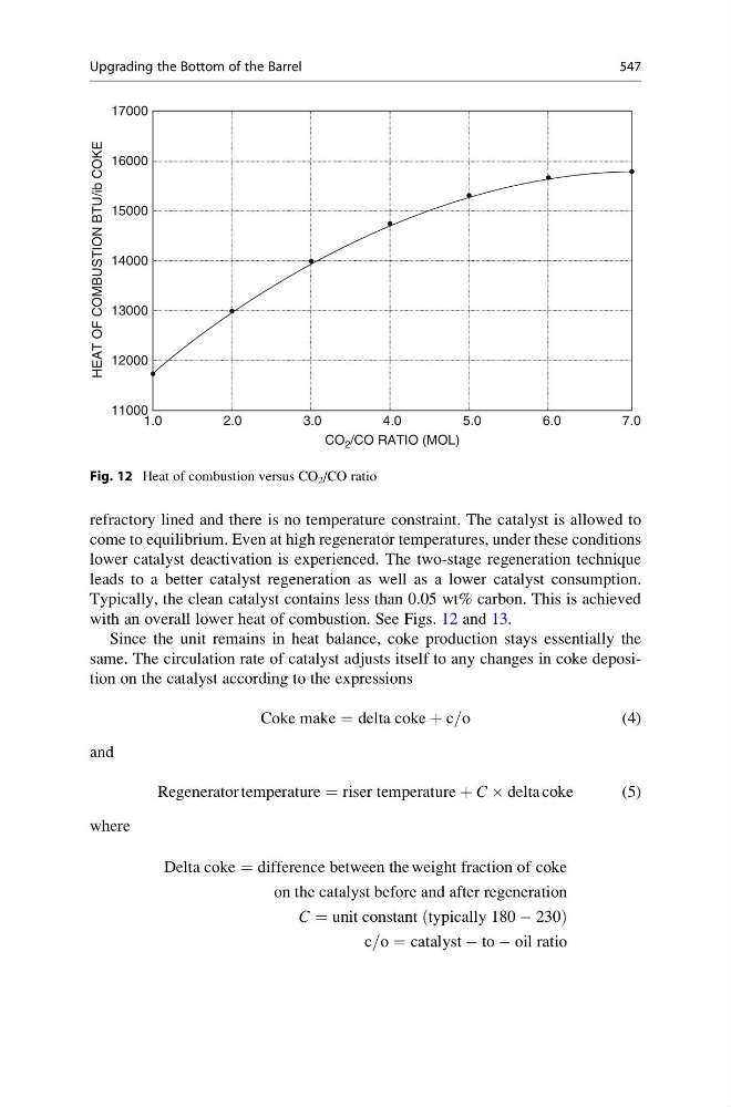
with an overall lower heat of combustion. See Figs. 12 and 13.
Since the unit remains in heat balance, coke production stays essentially the
same. The circulation rate of catalyst adjusts itself to any changes in coke deposition on the catalyst according to the expressions
Coke make ¼ delta coke þ c=o
(4)
and
Regenerator temperature ¼ riser temperature þ C Â delta coke
(5)
where
Delta coke ¼ difference between the weight fraction of coke
on the catalyst before and after regeneration
C ¼ unit constant typically 180 À 230
ð
Þ
c=o ¼ catalyst À to À oil ratio
17000
16000
15000
14000
13000
12000
HEAT OF COMBUSTION BTU/ib COKE
11000
1.0
2.0
3.0
CO 2 /CO RATIO (MOL)
4.0
5.0
6.0
7.0
Fig. 12 Heat of combustion versus CO 2 /CO ratio
Upgrading the Bottom of the Barrel
547
come to equilibrium. Even at high regenerator temperatures, under these conditions
lower catalyst deactivation is experienced. The two-stage regeneration technique
leads to a better catalyst regeneration as well as a lower catalyst consumption.
Typically, the clean catalyst contains less than 0.05 wt% carbon. This is achieved
with an overall lower heat of combustion. See Figs. 12 and 13.
Since the unit remains in heat balance, coke production stays essentially the
same. The circulation rate of catalyst adjusts itself to any changes in coke deposition on the catalyst according to the expressions
Coke make ¼ delta coke þ c=o
(4)
and
Regenerator temperature ¼ riser temperature þ C Â delta coke
(5)
where
Delta coke ¼ difference between the weight fraction of coke
on the catalyst before and after regeneration
C ¼ unit constant typically 180 À 230
ð
Þ
c=o ¼ catalyst À to À oil ratio
17000
16000
15000
14000
13000
12000
HEAT OF COMBUSTION BTU/ib COKE
11000
1.0
2.0
3.0
CO 2 /CO RATIO (MOL)
4.0
5.0
6.0
7.0
Fig. 12 Heat of combustion versus CO 2 /CO ratio
Upgrading the Bottom of the Barrel
547