

Two-Stage Regeneration and Regenerated Catalyst
Temperature Control
An important issue in the case of deep oil (residue) cracking is the handling of the
high coke laydown and the protection of the catalyst. One technique that limits the
severe conditions in regeneration of the spent catalyst is the two-stage regeneration.
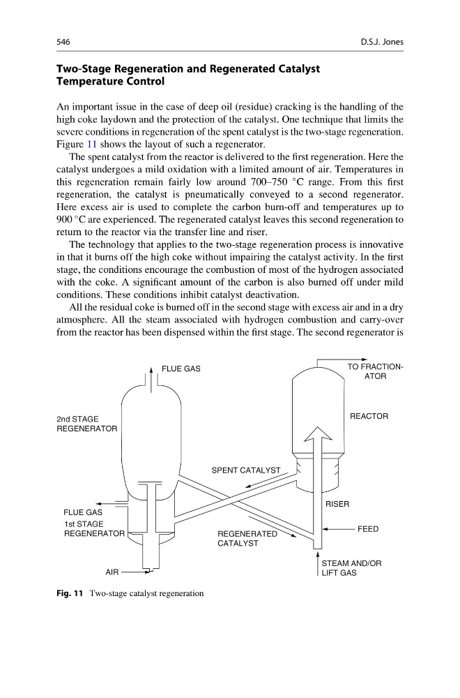
Figure 11 shows the layout of such a regenerator.
The spent catalyst from the reactor is delivered to the first regeneration. Here the
catalyst undergoes a mild oxidation with a limited amount of air. Temperatures in
this regeneration remain fairly low around 700–750
C range. From this first
regeneration, the catalyst is pneumatically conveyed to a second regenerator.
Here excess air is used to complete the carbon burn-off and temperatures up to
900
C are experienced. The regenerated catalyst leaves this second regeneration to
return to the reactor via the transfer line and riser.
The technology that applies to the two-stage regeneration process is innovative
in that it burns off the high coke without impairing the catalyst activity. In the first
stage, the conditions encourage the combustion of most of the hydrogen associated
with the coke. A significant amount of the carbon is also burned off under mild
conditions. These conditions inhibit catalyst deactivation.
All the residual coke is burned off in the second stage with excess air and in a dry
atmosphere. All the steam associated with hydrogen combustion and carry-over
from the reactor has been dispensed within the first stage. The second regenerator is
FLUE GAS
2nd STAGE
REGENERATOR
1st STAGE
REGENERATOR
FLUE GAS
AIR
REGENERATED
CATALYST
STEAM AND/OR
LIFT GAS
FEED
RISER
REACTOR
TO FRACTIONATOR
SPENT CATALYST
Fig. 11 Two-stage catalyst regeneration
546
D.S.J. Jones
Temperature Control
An important issue in the case of deep oil (residue) cracking is the handling of the
high coke laydown and the protection of the catalyst. One technique that limits the
severe conditions in regeneration of the spent catalyst is the two-stage regeneration.
Figure 11 shows the layout of such a regenerator.
The spent catalyst from the reactor is delivered to the first regeneration. Here the
catalyst undergoes a mild oxidation with a limited amount of air. Temperatures in
this regeneration remain fairly low around 700–750
C range. From this first
regeneration, the catalyst is pneumatically conveyed to a second regenerator.
Here excess air is used to complete the carbon burn-off and temperatures up to
900
C are experienced. The regenerated catalyst leaves this second regeneration to
return to the reactor via the transfer line and riser.
The technology that applies to the two-stage regeneration process is innovative
in that it burns off the high coke without impairing the catalyst activity. In the first
stage, the conditions encourage the combustion of most of the hydrogen associated
with the coke. A significant amount of the carbon is also burned off under mild
conditions. These conditions inhibit catalyst deactivation.
All the residual coke is burned off in the second stage with excess air and in a dry
atmosphere. All the steam associated with hydrogen combustion and carry-over
from the reactor has been dispensed within the first stage. The second regenerator is
FLUE GAS
2nd STAGE
REGENERATOR
1st STAGE
REGENERATOR
FLUE GAS
AIR
REGENERATED
CATALYST
STEAM AND/OR
LIFT GAS
FEED
RISER
REACTOR
TO FRACTIONATOR
SPENT CATALYST
Fig. 11 Two-stage catalyst regeneration
546
D.S.J. Jones