

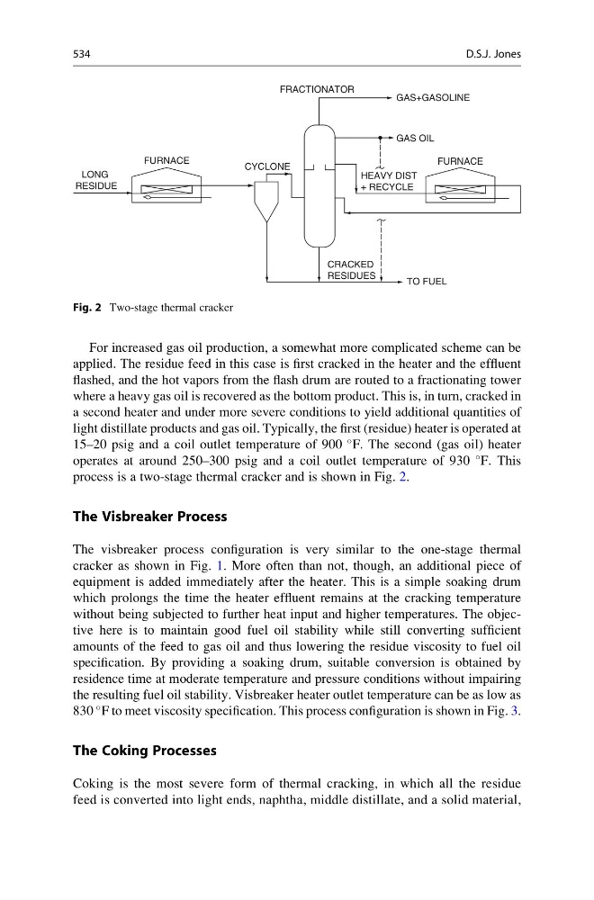
For increased gas oil production, a somewhat more complicated scheme can be
applied. The residue feed in this case is first cracked in the heater and the effluent
flashed, and the hot vapors from the flash drum are routed to a fractionating tower
where a heavy gas oil is recovered as the bottom product. This is, in turn, cracked in
a second heater and under more severe conditions to yield additional quantities of
light distillate products and gas oil. Typically, the first (residue) heater is operated at
15–20 psig and a coil outlet temperature of 900
F. The second (gas oil) heater
operates at around 250–300 psig and a coil outlet temperature of 930
F. This
process is a two-stage thermal cracker and is shown in Fig. 2.
The Visbreaker Process
The visbreaker process configuration is very similar to the one-stage thermal
cracker as shown in Fig. 1. More often than not, though, an additional piece of
equipment is added immediately after the heater. This is a simple soaking drum
which prolongs the time the heater effluent remains at the cracking temperature
without being subjected to further heat input and higher temperatures. The objective here is to maintain good fuel oil stability while still converting sufficient
amounts of the feed to gas oil and thus lowering the residue viscosity to fuel oil
specification. By providing a soaking drum, suitable conversion is obtained by
residence time at moderate temperature and pressure conditions without impairing
the resulting fuel oil stability. Visbreaker heater outlet temperature can be as low as
830
F to meet viscosity specification. This process configuration is shown in Fig. 3.
The Coking Processes
Coking is the most severe form of thermal cracking, in which all the residue
feed is converted into light ends, naphtha, middle distillate, and a solid material,
FURNACE
CYCLONE
FRACTIONATOR
GAS+GASOLINE
GAS OIL
FURNACE
HEAVY DIST
+ RECYCLE
CRACKED
RESIDUES
TO FUEL
LONG
RESIDUE
Fig. 2 Two-stage thermal cracker
534
D.S.J. Jones
applied. The residue feed in this case is first cracked in the heater and the effluent
flashed, and the hot vapors from the flash drum are routed to a fractionating tower
where a heavy gas oil is recovered as the bottom product. This is, in turn, cracked in
a second heater and under more severe conditions to yield additional quantities of
light distillate products and gas oil. Typically, the first (residue) heater is operated at
15–20 psig and a coil outlet temperature of 900
F. The second (gas oil) heater
operates at around 250–300 psig and a coil outlet temperature of 930
F. This
process is a two-stage thermal cracker and is shown in Fig. 2.
The Visbreaker Process
The visbreaker process configuration is very similar to the one-stage thermal
cracker as shown in Fig. 1. More often than not, though, an additional piece of
equipment is added immediately after the heater. This is a simple soaking drum
which prolongs the time the heater effluent remains at the cracking temperature
without being subjected to further heat input and higher temperatures. The objective here is to maintain good fuel oil stability while still converting sufficient
amounts of the feed to gas oil and thus lowering the residue viscosity to fuel oil
specification. By providing a soaking drum, suitable conversion is obtained by
residence time at moderate temperature and pressure conditions without impairing
the resulting fuel oil stability. Visbreaker heater outlet temperature can be as low as
830
F to meet viscosity specification. This process configuration is shown in Fig. 3.
The Coking Processes
Coking is the most severe form of thermal cracking, in which all the residue
feed is converted into light ends, naphtha, middle distillate, and a solid material,
FURNACE
CYCLONE
FRACTIONATOR
GAS+GASOLINE
GAS OIL
FURNACE
HEAVY DIST
+ RECYCLE
CRACKED
RESIDUES
TO FUEL
LONG
RESIDUE
Fig. 2 Two-stage thermal cracker
534
D.S.J. Jones