

HF Alkylation
Process Flow Description
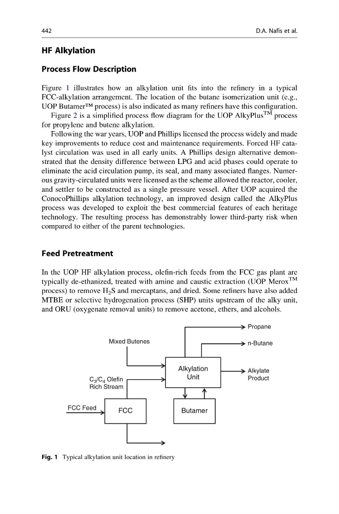
Figure 1 illustrates how an alkylation unit fits into the refinery in a typical
FCC-alkylation arrangement. The location of the butane isomerization unit (e.g.,
UOP Butamer™ process) is also indicated as many refiners have this configuration.
Figure 2 is a simplified process flow diagram for the UOP AlkyPlus
TM process
for propylene and butene alkylation.
Following the war years, UOP and Phillips licensed the process widely and made
key improvements to reduce cost and maintenance requirements. Forced HF catalyst circulation was used in all early units. A Phillips design alternative demonstrated that the density difference between LPG and acid phases could operate to
eliminate the acid circulation pump, its seal, and many associated flanges. Numerous gravity-circulated units were licensed as the scheme allowed the reactor, cooler,
and settler to be constructed as a single pressure vessel. After UOP acquired the
ConocoPhillips alkylation technology, an improved design called the AlkyPlus
process was developed to exploit the best commercial features of each heritage
technology. The resulting process has demonstrably lower third-party risk when
compared to either of the parent technologies.
Feed Pretreatment
In the UOP HF alkylation process, olefin-rich feeds from the FCC gas plant are
typically de-ethanized, treated with amine and caustic extraction (UOP Merox
TM
process) to remove H 2 S and mercaptans, and dried. Some refiners have also added
MTBE or selective hydrogenation process (SHP) units upstream of the alky unit,
and ORU (oxygenate removal units) to remove acetone, ethers, and alcohols.
Alkylation
Unit
Butamer
FCC
FCC Feed
Mixed Butenes
C 3 /C 4 Olefin
Rich Stream
Propane
n-Butane
Alkylate
Product
Fig. 1 Typical alkylation unit location in refinery
442
D.A. Nafis et al.
Process Flow Description
Figure 1 illustrates how an alkylation unit fits into the refinery in a typical
FCC-alkylation arrangement. The location of the butane isomerization unit (e.g.,
UOP Butamer™ process) is also indicated as many refiners have this configuration.
Figure 2 is a simplified process flow diagram for the UOP AlkyPlus
TM process
for propylene and butene alkylation.
Following the war years, UOP and Phillips licensed the process widely and made
key improvements to reduce cost and maintenance requirements. Forced HF catalyst circulation was used in all early units. A Phillips design alternative demonstrated that the density difference between LPG and acid phases could operate to
eliminate the acid circulation pump, its seal, and many associated flanges. Numerous gravity-circulated units were licensed as the scheme allowed the reactor, cooler,
and settler to be constructed as a single pressure vessel. After UOP acquired the
ConocoPhillips alkylation technology, an improved design called the AlkyPlus
process was developed to exploit the best commercial features of each heritage
technology. The resulting process has demonstrably lower third-party risk when
compared to either of the parent technologies.
Feed Pretreatment
In the UOP HF alkylation process, olefin-rich feeds from the FCC gas plant are
typically de-ethanized, treated with amine and caustic extraction (UOP Merox
TM
process) to remove H 2 S and mercaptans, and dried. Some refiners have also added
MTBE or selective hydrogenation process (SHP) units upstream of the alky unit,
and ORU (oxygenate removal units) to remove acetone, ethers, and alcohols.
Alkylation
Unit
Butamer
FCC
FCC Feed
Mixed Butenes
C 3 /C 4 Olefin
Rich Stream
Propane
n-Butane
Alkylate
Product
Fig. 1 Typical alkylation unit location in refinery
442
D.A. Nafis et al.