

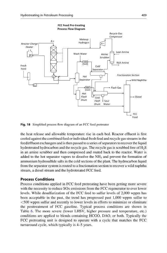
the heat release and allowable temperature rise in each bed. Reactor effluent is first
cooled against the combined feed or individual fresh feed and recycle gas streams in the
feed/effluent exchangers and is then passed to a series of separators to recover the liquid
hydrotreated hydrocarbon and the recycle gas. The recycle gas is scrubbed free of H 2 S
in an amine scrubber and then compressed and routed back to the reactor. Water is
added to the hot separator vapors to dissolve the NH 3 and prevent the formation of
ammonium hydrosulfide salts in the cold sections of the plant. The hydrocarbon liquid
from the separator system is routed to a fractionation section to recover a wild naphtha
stream, a diesel stream and the hydrotreated FCC feed.
Process Conditions
Process conditions applied in FCC feed pretreating have been getting more severe
with the necessity to reduce SOx emissions from the FCC regenerator to ever lower
levels. While desulfurization of the FCC feed to sulfur levels of 2,000 wppm has
been acceptable in the past, the trend has progressed past 1,000 wppm sulfur to
<500 wppm sulfur and recently to lower levels in efforts to minimize or eliminate
the posttreatment of FCC gasoline. Typical process conditions are shown in
Table 6. The more severe (lower LHSV, higher pressure and temperature, etc.)
conditions are applied to blends containing HCGO, DAO, or both. Typically the
FCC pretreating unit is designed to operate with a cycle that matches the FCC
turnaround cycle, which typically is 4–5 years.
FCC Feed Pre-treating
Process Flow Diagram
Amine
Scrubber
Lean Amine
Rich Amine
Wash Water
Sour
Water
Makeup
Hydrogen
Flash Gas
Hot
Separator
Cold
Separator
Hot
Flash
Drum
Cold
Flash
Drum
Recycle Gas
Compressor
Reactor Charge
Heater
R-1
Fresh
Feed
Wild Naphtha
Diesel
FCC
Feed
Fractionaton Section
Fig. 18 Simplified process flow diagram of an FCC feed pretreater
Hydrotreating in Petroleum Processing
409
cooled against the combined feed or individual fresh feed and recycle gas streams in the
feed/effluent exchangers and is then passed to a series of separators to recover the liquid
hydrotreated hydrocarbon and the recycle gas. The recycle gas is scrubbed free of H 2 S
in an amine scrubber and then compressed and routed back to the reactor. Water is
added to the hot separator vapors to dissolve the NH 3 and prevent the formation of
ammonium hydrosulfide salts in the cold sections of the plant. The hydrocarbon liquid
from the separator system is routed to a fractionation section to recover a wild naphtha
stream, a diesel stream and the hydrotreated FCC feed.
Process Conditions
Process conditions applied in FCC feed pretreating have been getting more severe
with the necessity to reduce SOx emissions from the FCC regenerator to ever lower
levels. While desulfurization of the FCC feed to sulfur levels of 2,000 wppm has
been acceptable in the past, the trend has progressed past 1,000 wppm sulfur to
<500 wppm sulfur and recently to lower levels in efforts to minimize or eliminate
the posttreatment of FCC gasoline. Typical process conditions are shown in
Table 6. The more severe (lower LHSV, higher pressure and temperature, etc.)
conditions are applied to blends containing HCGO, DAO, or both. Typically the
FCC pretreating unit is designed to operate with a cycle that matches the FCC
turnaround cycle, which typically is 4–5 years.
FCC Feed Pre-treating
Process Flow Diagram
Amine
Scrubber
Lean Amine
Rich Amine
Wash Water
Sour
Water
Makeup
Hydrogen
Flash Gas
Hot
Separator
Cold
Separator
Hot
Flash
Drum
Cold
Flash
Drum
Recycle Gas
Compressor
Reactor Charge
Heater
R-1
Fresh
Feed
Wild Naphtha
Diesel
FCC
Feed
Fractionaton Section
Fig. 18 Simplified process flow diagram of an FCC feed pretreater
Hydrotreating in Petroleum Processing
409