

Hydrodesulfurization, hydrodenitrogenation, and saturation reactions are similar
to those occurring in distillate hydrotreating except the reacting species are of
higher molecular weight.
Feedstocks
Feedstocks to an FCC feed pretreating unit may include vacuum gas oils (VGO) as
well as heavy coker gas oil (HCGO). Sulfur contents may range from 0.5 to 3 wt%
and nitrogen from 500 to 3,000 wppm. The higher values, especially for nitrogen,
are found in HCGO. HCGO additionally contains olefins with bromine numbers
ranging up to ~20. The olefinic nature of the HCGO feed requires consideration of
catalyst bed distribution and temperature management due to the highly exothermic
nature of the very rapid olefin saturation reactions.
Process Configuration
A simplified process flow diagram of a typical FCC feed pretreater is shown in Fig. 18.
The feed is pumped from the feed surge drum and mixed with recycle gas, and the
mixture is then heated in a bank of feed/effluent exchangers and then passes to the
reactor charge heater where it is heated to reaction temperature and then enters the
reactor. The reactor is shown with three beds of catalyst with recycle gas being routed
to the quench zones to reduce the temperature of the effluent of each bed to the desired
inlet temperature of the next catalyst bed. The number of catalyst beds is dependent on
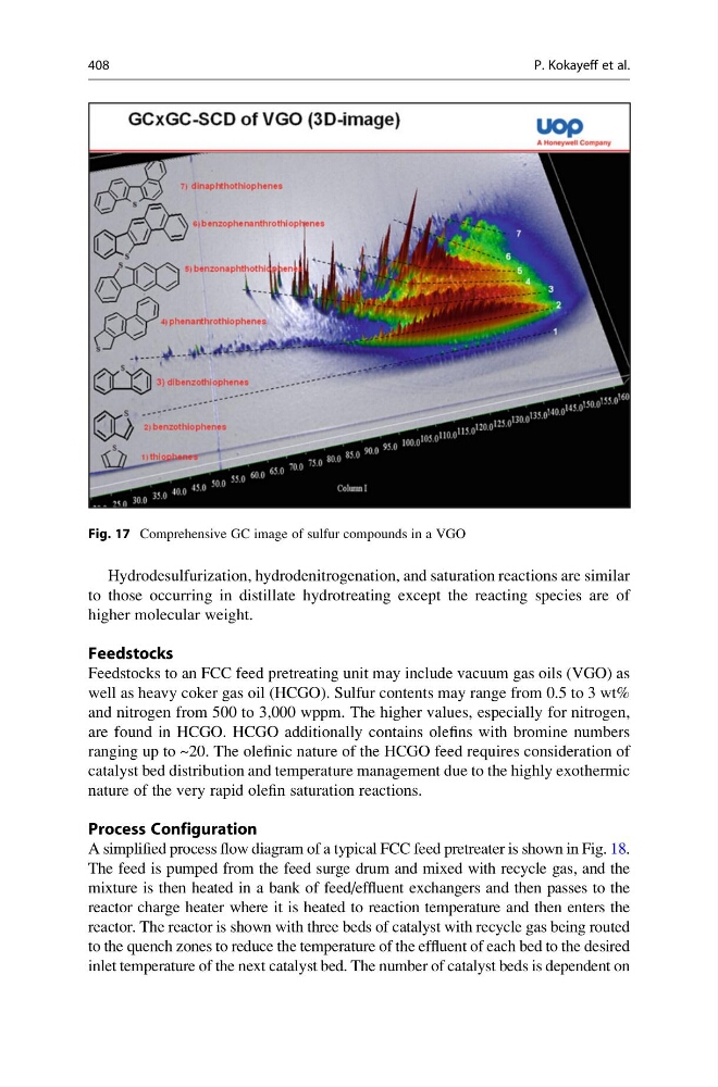
Fig. 17 Comprehensive GC image of sulfur compounds in a VGO
408
P. Kokayeff et al.
to those occurring in distillate hydrotreating except the reacting species are of
higher molecular weight.
Feedstocks
Feedstocks to an FCC feed pretreating unit may include vacuum gas oils (VGO) as
well as heavy coker gas oil (HCGO). Sulfur contents may range from 0.5 to 3 wt%
and nitrogen from 500 to 3,000 wppm. The higher values, especially for nitrogen,
are found in HCGO. HCGO additionally contains olefins with bromine numbers
ranging up to ~20. The olefinic nature of the HCGO feed requires consideration of
catalyst bed distribution and temperature management due to the highly exothermic
nature of the very rapid olefin saturation reactions.
Process Configuration
A simplified process flow diagram of a typical FCC feed pretreater is shown in Fig. 18.
The feed is pumped from the feed surge drum and mixed with recycle gas, and the
mixture is then heated in a bank of feed/effluent exchangers and then passes to the
reactor charge heater where it is heated to reaction temperature and then enters the
reactor. The reactor is shown with three beds of catalyst with recycle gas being routed
to the quench zones to reduce the temperature of the effluent of each bed to the desired
inlet temperature of the next catalyst bed. The number of catalyst beds is dependent on
Fig. 17 Comprehensive GC image of sulfur compounds in a VGO
408
P. Kokayeff et al.