

Process Configuration
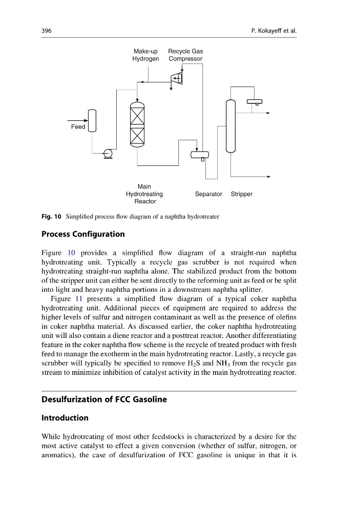
Figure 10 provides a simplified flow diagram of a straight-run naphtha
hydrotreating unit. Typically a recycle gas scrubber is not required when
hydrotreating straight-run naphtha alone. The stabilized product from the bottom
of the stripper unit can either be sent directly to the reforming unit as feed or be split
into light and heavy naphtha portions in a downstream naphtha splitter.
Figure 11 presents a simplified flow diagram of a typical coker naphtha
hydrotreating unit. Additional pieces of equipment are required to address the
higher levels of sulfur and nitrogen contaminant as well as the presence of olefins
in coker naphtha material. As discussed earlier, the coker naphtha hydrotreating
unit will also contain a diene reactor and a posttreat reactor. Another differentiating
feature in the coker naphtha flow scheme is the recycle of treated product with fresh
feed to manage the exotherm in the main hydrotreating reactor. Lastly, a recycle gas
scrubber will typically be specified to remove H 2 S and NH 3 from the recycle gas
stream to minimize inhibition of catalyst activity in the main hydrotreating reactor.
Desulfurization of FCC Gasoline
Introduction
While hydrotreating of most other feedstocks is characterized by a desire for the
most active catalyst to effect a given conversion (whether of sulfur, nitrogen, or
aromatics), the case of desulfurization of FCC gasoline is unique in that it is
Separator
Recycle Gas
Compressor
Make-up
Hydrogen
Main
Hydrotreating
Reactor
Feed
Stripper
Fig. 10 Simplified process flow diagram of a naphtha hydrotreater
396
P. Kokayeff et al.
Figure 10 provides a simplified flow diagram of a straight-run naphtha
hydrotreating unit. Typically a recycle gas scrubber is not required when
hydrotreating straight-run naphtha alone. The stabilized product from the bottom
of the stripper unit can either be sent directly to the reforming unit as feed or be split
into light and heavy naphtha portions in a downstream naphtha splitter.
Figure 11 presents a simplified flow diagram of a typical coker naphtha
hydrotreating unit. Additional pieces of equipment are required to address the
higher levels of sulfur and nitrogen contaminant as well as the presence of olefins
in coker naphtha material. As discussed earlier, the coker naphtha hydrotreating
unit will also contain a diene reactor and a posttreat reactor. Another differentiating
feature in the coker naphtha flow scheme is the recycle of treated product with fresh
feed to manage the exotherm in the main hydrotreating reactor. Lastly, a recycle gas
scrubber will typically be specified to remove H 2 S and NH 3 from the recycle gas
stream to minimize inhibition of catalyst activity in the main hydrotreating reactor.
Desulfurization of FCC Gasoline
Introduction
While hydrotreating of most other feedstocks is characterized by a desire for the
most active catalyst to effect a given conversion (whether of sulfur, nitrogen, or
aromatics), the case of desulfurization of FCC gasoline is unique in that it is
Separator
Recycle Gas
Compressor
Make-up
Hydrogen
Main
Hydrotreating
Reactor
Feed
Stripper
Fig. 10 Simplified process flow diagram of a naphtha hydrotreater
396
P. Kokayeff et al.