

Two-Stage Recycle Hydrocracking
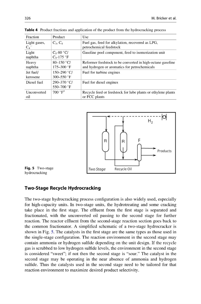
The two-stage hydrocracking process configuration is also widely used, especially
for high-capacity units. In two-stage units, the hydrotreating and some cracking
take place in the first stage. The effluent from the first stage is separated and
fractionated, with the unconverted oil passing to the second stage for further
reaction. The reactor effluent from the second-stage reaction section goes back to
the common fractionator. A simplified schematic of a two-stage hydrocracker is
shown in Fig. 5. The catalysts in the first stage are the same types as those used in
the single-stage configuration. The reaction environment in the second stage may
contain ammonia or hydrogen sulfide depending on the unit design. If the recycle
gas is scrubbed to low hydrogen sulfide levels, the environment in the second stage
is considered “sweet”; if not then the second stage is “sour.” The catalyst in the
second stage may be operating in the near absence of ammonia and hydrogen
sulfide. Thus the catalysts used in the second stage need to be tailored for that
reaction environment to maximize desired product selectivity.
Fig. 5 Two-stage
hydrocracking
Table 4 Product fractions and application of the product from the hydrocracking process
Fraction
Product
Use
Light gases,
C 4
À
C 3 , C 4
Fuel gas, feed for alkylation, recovered as LPG,
petrochemical feedstock
Light
naphtha
C 5 -80
C/
C 5 -175
F
Gasoline pool component, feed to isomerization unit
Heavy
naphtha
80–150
C/
175–300
F
Reformer feedstock to be converted in high-octane gasoline
and hydrogen or aromatics for petrochemicals
Jet fuel/
kerosene
150–290
C/
300–550
F
Fuel for turbine engines
Diesel fuel
290–370
C/
550–700
F
Fuel for diesel engines
Unconverted
oil
700
F
+
Recycle feed or feedstock for lube plants or ethylene plants
or FCC plants
326
M. Bricker et al.
The two-stage hydrocracking process configuration is also widely used, especially
for high-capacity units. In two-stage units, the hydrotreating and some cracking
take place in the first stage. The effluent from the first stage is separated and
fractionated, with the unconverted oil passing to the second stage for further
reaction. The reactor effluent from the second-stage reaction section goes back to
the common fractionator. A simplified schematic of a two-stage hydrocracker is
shown in Fig. 5. The catalysts in the first stage are the same types as those used in
the single-stage configuration. The reaction environment in the second stage may
contain ammonia or hydrogen sulfide depending on the unit design. If the recycle
gas is scrubbed to low hydrogen sulfide levels, the environment in the second stage
is considered “sweet”; if not then the second stage is “sour.” The catalyst in the
second stage may be operating in the near absence of ammonia and hydrogen
sulfide. Thus the catalysts used in the second stage need to be tailored for that
reaction environment to maximize desired product selectivity.
Fig. 5 Two-stage
hydrocracking
Table 4 Product fractions and application of the product from the hydrocracking process
Fraction
Product
Use
Light gases,
C 4
À
C 3 , C 4
Fuel gas, feed for alkylation, recovered as LPG,
petrochemical feedstock
Light
naphtha
C 5 -80
C/
C 5 -175
F
Gasoline pool component, feed to isomerization unit
Heavy
naphtha
80–150
C/
175–300
F
Reformer feedstock to be converted in high-octane gasoline
and hydrogen or aromatics for petrochemicals
Jet fuel/
kerosene
150–290
C/
300–550
F
Fuel for turbine engines
Diesel fuel
290–370
C/
550–700
F
Fuel for diesel engines
Unconverted
oil
700
F
+
Recycle feed or feedstock for lube plants or ethylene plants
or FCC plants
326
M. Bricker et al.