

cracking configurations, the first catalyst (a hydrotreating catalyst) converts
organic sulfur and nitrogen from hetero-compounds in the feedstock to hydrogen
sulfide and ammonia, respectively. The deleterious effect of gas-phase H 2 S and
NH 3 on hydrocracking catalysts is considerably less than that of the corresponding
organic hetero-compounds in the liquid phase. The hydrotreating catalyst also
facilitates the hydrogenation of aromatics. In the single-stage configuration, the
products from the hydrotreating reaction zone are passed over a hydrocracking
catalyst where most of the hydrocracking takes place. The conversion occurs
in the presence of NH 3 , H 2 S, and small amounts of unconverted amounts of
hetero-compounds. The hydrotreating catalyst is designed to convert the
hetero-compounds in the feedstock. Typically, such catalysts comprise sulfided
molybdenum and nickel on an alumina support. The reactor operates at
temperatures varying from 570 to 800
F (300–425
C) and hydrogen pressures
between 1,250 and 2,500 psig (85–170 bar). Under these conditions, heteroatom
elimination, significant hydrogenation, and some cracking also take place.
The cracking catalyst operates at the same hydrogen pressures but at temperatures
varying from 570 to as high as 840
F (300–450
C) for amorphous hydrocracking
catalysts and up to 440
C (825
F) for zeolite-containing catalysts.
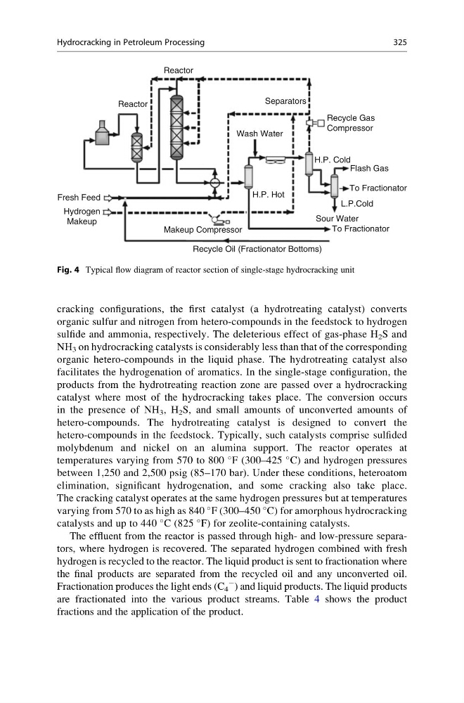
The effluent from the reactor is passed through high- and low-pressure separators, where hydrogen is recovered. The separated hydrogen combined with fresh
hydrogen is recycled to the reactor. The liquid product is sent to fractionation where
the final products are separated from the recycled oil and any unconverted oil.
Fractionation produces the light ends (C 4
À
) and liquid products. The liquid products
are fractionated into the various product streams. Table 4 shows the product
fractions and the application of the product.
Separators
Reactor
Reactor
Makeup Compressor
Recycle Oil (Fractionator Bottoms)
To Fractionator
Sour Water
L.P.Cold
To Fractionator
Flash Gas
H.P. Cold
Recycle Gas
Compressor
Wash Water
H.P. Hot
Fresh Feed
Hydrogen
Makeup
Fig. 4 Typical flow diagram of reactor section of single-stage hydrocracking unit
Hydrocracking in Petroleum Processing
325
organic sulfur and nitrogen from hetero-compounds in the feedstock to hydrogen
sulfide and ammonia, respectively. The deleterious effect of gas-phase H 2 S and
NH 3 on hydrocracking catalysts is considerably less than that of the corresponding
organic hetero-compounds in the liquid phase. The hydrotreating catalyst also
facilitates the hydrogenation of aromatics. In the single-stage configuration, the
products from the hydrotreating reaction zone are passed over a hydrocracking
catalyst where most of the hydrocracking takes place. The conversion occurs
in the presence of NH 3 , H 2 S, and small amounts of unconverted amounts of
hetero-compounds. The hydrotreating catalyst is designed to convert the
hetero-compounds in the feedstock. Typically, such catalysts comprise sulfided
molybdenum and nickel on an alumina support. The reactor operates at
temperatures varying from 570 to 800
F (300–425
C) and hydrogen pressures
between 1,250 and 2,500 psig (85–170 bar). Under these conditions, heteroatom
elimination, significant hydrogenation, and some cracking also take place.
The cracking catalyst operates at the same hydrogen pressures but at temperatures
varying from 570 to as high as 840
F (300–450
C) for amorphous hydrocracking
catalysts and up to 440
C (825
F) for zeolite-containing catalysts.
The effluent from the reactor is passed through high- and low-pressure separators, where hydrogen is recovered. The separated hydrogen combined with fresh
hydrogen is recycled to the reactor. The liquid product is sent to fractionation where
the final products are separated from the recycled oil and any unconverted oil.
Fractionation produces the light ends (C 4
À
) and liquid products. The liquid products
are fractionated into the various product streams. Table 4 shows the product
fractions and the application of the product.
Separators
Reactor
Reactor
Makeup Compressor
Recycle Oil (Fractionator Bottoms)
To Fractionator
Sour Water
L.P.Cold
To Fractionator
Flash Gas
H.P. Cold
Recycle Gas
Compressor
Wash Water
H.P. Hot
Fresh Feed
Hydrogen
Makeup
Fig. 4 Typical flow diagram of reactor section of single-stage hydrocracking unit
Hydrocracking in Petroleum Processing
325