

catalyst and air, the mix temperature, the catalyst type and activity, and the number
of cycles the catalyst makes through the system. This latter fact implies there is an
optimum unit inventory for a given processing capacity.
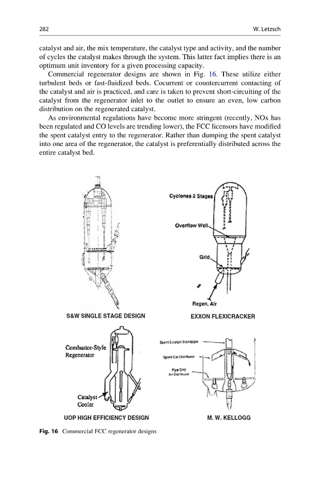
Commercial regenerator designs are shown in Fig. 16. These utilize either
turbulent beds or fast-fluidized beds. Cocurrent or countercurrent contacting of
the catalyst and air is practiced, and care is taken to prevent short-circuiting of the
catalyst from the regenerator inlet to the outlet to ensure an even, low carbon
distribution on the regenerated catalyst.
As environmental regulations have become more stringent (recently, NOx has
been regulated and CO levels are trending lower), the FCC licensors have modified
the spent catalyst entry to the regenerator. Rather than dumping the spent catalyst
into one area of the regenerator, the catalyst is preferentially distributed across the
entire catalyst bed.
Fig. 16 Commercial FCC regenerator designs
282
W. Letzsch
of cycles the catalyst makes through the system. This latter fact implies there is an
optimum unit inventory for a given processing capacity.
Commercial regenerator designs are shown in Fig. 16. These utilize either
turbulent beds or fast-fluidized beds. Cocurrent or countercurrent contacting of
the catalyst and air is practiced, and care is taken to prevent short-circuiting of the
catalyst from the regenerator inlet to the outlet to ensure an even, low carbon
distribution on the regenerated catalyst.
As environmental regulations have become more stringent (recently, NOx has
been regulated and CO levels are trending lower), the FCC licensors have modified
the spent catalyst entry to the regenerator. Rather than dumping the spent catalyst
into one area of the regenerator, the catalyst is preferentially distributed across the
entire catalyst bed.
Fig. 16 Commercial FCC regenerator designs
282
W. Letzsch