

discharged to the atmosphere. Typical regenerator temperatures in these two operating modes are 1,150–1,250
F (620–675
C) and 1,275–1,350
F (690–732
C),
respectively, for partial and complete combustion.
The spent catalyst slide valve controls the catalyst level in the stripper or reactor
bed if one is being used. No direct control of the regenerator catalyst bed level is made,
and its level floats depending on the catalyst losses and the catalyst withdrawal and
addition policies. Most units are capable of retaining most of the fresh catalyst added
daily and must periodically withdraw equilibrium catalyst to keep the regenerator
level from getting too high. The regenerator is used as the “floating” vessel because
it is larger and it is desirable to withdraw regenerated rather than spent catalyst.
With the advent of computers and advanced process controllers, many refinements to the basic control scheme are possible. The control system has been
extended to include the gas plant as well as the reactor/regenerator system. The
biggest benefits come from operating closer to several limits at one time. Better
analysis of the feedstocks could allow feed-forward control in the future. While
these control systems can improve refining profitability from 20 to 40 cents/barrel
processed, they require more instrumentation, which must be maintained to achieve
the stated benefits.
Reaction Chemistry and Mechanisms
Many studies have been performed elucidating the difference between thermal and
catalytic cracking. Two separate reaction mechanisms are attributed to the methods
of cracking, i.e., thermal cracking goes through free radicals and catalytic cracking
proceeds via carbenium ions. The latter are generally associated with the Bro ¨nsted
acid sites on the catalyst. In Table 6, the major differences between the two
mechanisms are shown. Thermal cracking is minimized as much as possible in
current FCC units by the use of advanced equipment such as radial feed injectors,
riser termination devices, and post-riser quench. Catalyst selection is also critical.
There are many reactions that occur during the cracking process. These are listed
below as primary or secondary reactions (Table 7 and 8). Most of the secondary
reactions are undesirable and are controlled through reactor and catalyst design.
Numerous cracking reactions occur with the large feed molecules before the desired
products are achieved. Typical feeds to a catalytic cracking unit contain molecules
boiling above the diesel end point (650–700
F or 343–371
C) and may boil as high
as 1,500
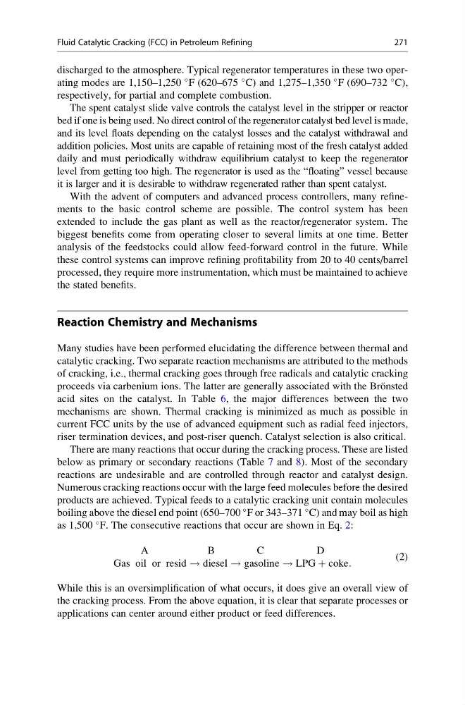
F. The consecutive reactions that occur are shown in Eq. 2:
A
B
C
D
Gas oil or resid ! diesel ! gasoline ! LPG þ coke:
(2)
While this is an oversimplification of what occurs, it does give an overall view of
the cracking process. From the above equation, it is clear that separate processes or
applications can center around either product or feed differences.
Fluid Catalytic Cracking (FCC) in Petroleum Refining
271
F (620–675
C) and 1,275–1,350
F (690–732
C),
respectively, for partial and complete combustion.
The spent catalyst slide valve controls the catalyst level in the stripper or reactor
bed if one is being used. No direct control of the regenerator catalyst bed level is made,
and its level floats depending on the catalyst losses and the catalyst withdrawal and
addition policies. Most units are capable of retaining most of the fresh catalyst added
daily and must periodically withdraw equilibrium catalyst to keep the regenerator
level from getting too high. The regenerator is used as the “floating” vessel because
it is larger and it is desirable to withdraw regenerated rather than spent catalyst.
With the advent of computers and advanced process controllers, many refinements to the basic control scheme are possible. The control system has been
extended to include the gas plant as well as the reactor/regenerator system. The
biggest benefits come from operating closer to several limits at one time. Better
analysis of the feedstocks could allow feed-forward control in the future. While
these control systems can improve refining profitability from 20 to 40 cents/barrel
processed, they require more instrumentation, which must be maintained to achieve
the stated benefits.
Reaction Chemistry and Mechanisms
Many studies have been performed elucidating the difference between thermal and
catalytic cracking. Two separate reaction mechanisms are attributed to the methods
of cracking, i.e., thermal cracking goes through free radicals and catalytic cracking
proceeds via carbenium ions. The latter are generally associated with the Bro ¨nsted
acid sites on the catalyst. In Table 6, the major differences between the two
mechanisms are shown. Thermal cracking is minimized as much as possible in
current FCC units by the use of advanced equipment such as radial feed injectors,
riser termination devices, and post-riser quench. Catalyst selection is also critical.
There are many reactions that occur during the cracking process. These are listed
below as primary or secondary reactions (Table 7 and 8). Most of the secondary
reactions are undesirable and are controlled through reactor and catalyst design.
Numerous cracking reactions occur with the large feed molecules before the desired
products are achieved. Typical feeds to a catalytic cracking unit contain molecules
boiling above the diesel end point (650–700
F or 343–371
C) and may boil as high
as 1,500
F. The consecutive reactions that occur are shown in Eq. 2:
A
B
C
D
Gas oil or resid ! diesel ! gasoline ! LPG þ coke:
(2)
While this is an oversimplification of what occurs, it does give an overall view of
the cracking process. From the above equation, it is clear that separate processes or
applications can center around either product or feed differences.
Fluid Catalytic Cracking (FCC) in Petroleum Refining
271