

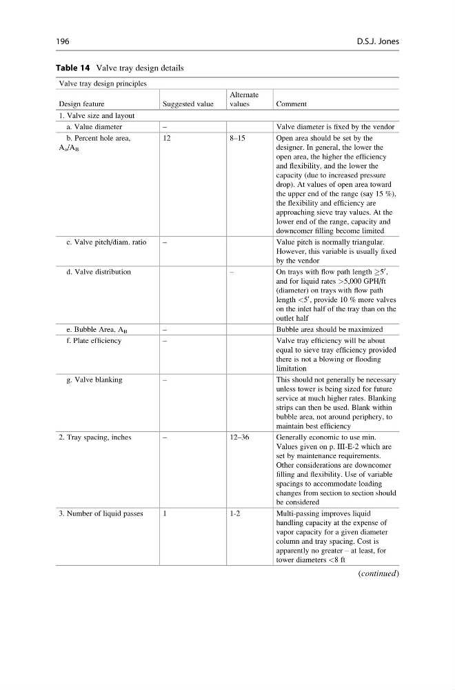
Table 14 Valve tray design details
Valve tray design principles
Design feature
Suggested value
Alternate
values
Comment
1. Valve size and layout
a. Value diameter
–
Valve diameter is fixed by the vendor
b. Percent hole area,
A o /A B
12
8–15
Open area should be set by the
designer. In general, the lower the
open area, the higher the efficiency
and flexibility, and the lower the
capacity (due to increased pressure
drop). At values of open area toward
the upper end of the range (say 15 %),
the flexibility and efficiency are
approaching sieve tray values. At the
lower end of the range, capacity and
downcomer filling become limited
c. Valve pitch/diam. ratio
–
Value pitch is normally triangular.
However, this variable is usually fixed
by the vendor
d. Valve distribution
–
On trays with flow path length !5
0 ,
and for liquid rates >5,000 GPH/ft
(diameter) on trays with flow path
length <5
0 , provide 10 % more valves
on the inlet half of the tray than on the
outlet half
e. Bubble Area, A B
–
Bubble area should be maximized
f. Plate efficiency
–
Valve tray efficiency will be about
equal to sieve tray efficiency provided
there is not a blowing or flooding
limitation
g. Valve blanking
–
This should not generally be necessary
unless tower is being sized for future
service at much higher rates. Blanking
strips can then be used. Blank within
bubble area, not around periphery, to
maintain best efficiency
2. Tray spacing, inches
–
12–36
Generally economic to use min.
Values given on p. III-E-2 which are
set by maintenance requirements.
Other considerations are downcomer
filling and flexibility. Use of variable
spacings to accommodate loading
changes from section to section should
be considered
3. Number of liquid passes
1
1-2
Multi-passing improves liquid
handling capacity at the expense of
vapor capacity for a given diameter
column and tray spacing. Cost is
apparently no greater – at least, for
tower diameters <8 ft
(continued)
196
D.S.J. Jones
Valve tray design principles
Design feature
Suggested value
Alternate
values
Comment
1. Valve size and layout
a. Value diameter
–
Valve diameter is fixed by the vendor
b. Percent hole area,
A o /A B
12
8–15
Open area should be set by the
designer. In general, the lower the
open area, the higher the efficiency
and flexibility, and the lower the
capacity (due to increased pressure
drop). At values of open area toward
the upper end of the range (say 15 %),
the flexibility and efficiency are
approaching sieve tray values. At the
lower end of the range, capacity and
downcomer filling become limited
c. Valve pitch/diam. ratio
–
Value pitch is normally triangular.
However, this variable is usually fixed
by the vendor
d. Valve distribution
–
On trays with flow path length !5
0 ,
and for liquid rates >5,000 GPH/ft
(diameter) on trays with flow path
length <5
0 , provide 10 % more valves
on the inlet half of the tray than on the
outlet half
e. Bubble Area, A B
–
Bubble area should be maximized
f. Plate efficiency
–
Valve tray efficiency will be about
equal to sieve tray efficiency provided
there is not a blowing or flooding
limitation
g. Valve blanking
–
This should not generally be necessary
unless tower is being sized for future
service at much higher rates. Blanking
strips can then be used. Blank within
bubble area, not around periphery, to
maintain best efficiency
2. Tray spacing, inches
–
12–36
Generally economic to use min.
Values given on p. III-E-2 which are
set by maintenance requirements.
Other considerations are downcomer
filling and flexibility. Use of variable
spacings to accommodate loading
changes from section to section should
be considered
3. Number of liquid passes
1
1-2
Multi-passing improves liquid
handling capacity at the expense of
vapor capacity for a given diameter
column and tray spacing. Cost is
apparently no greater – at least, for
tower diameters <8 ft
(continued)
196
D.S.J. Jones