

Process Description
This process is often integrated with the atmospheric crude distillation unit as far as
heat transfer is concerned. Generally the atmospheric residue from the CDU is
routed hot to the fired heater of the vacuum unit (Fig. 25).
The atmospheric residue is further distilled to provide the heavy distillate
streams used for producing lube oil or as feed to conversion units. This distillation
however has to be conducted under subatmospheric pressure conditions. The
temperature required for vaporizing the residue at atmospheric pressure would be
too high and the crude would crack.
The process follows very much the same pattern as the atmospheric distillation.
Should the cold feed be pumped from storage, it is heat exchanged against hot
product and pumparound streams before being vaporized in the distillation unit
heater. Normally, though, the feed is pumped hot directly from the CDU’s residue
stripper to the vacuum unit’s heater. Thereafter the distillate vapors are condensed
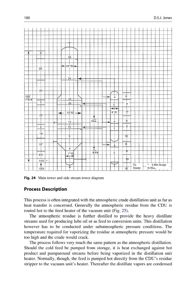
Fig. 24 Main tower and side stream tower diagram
180
D.S.J. Jones
This process is often integrated with the atmospheric crude distillation unit as far as
heat transfer is concerned. Generally the atmospheric residue from the CDU is
routed hot to the fired heater of the vacuum unit (Fig. 25).
The atmospheric residue is further distilled to provide the heavy distillate
streams used for producing lube oil or as feed to conversion units. This distillation
however has to be conducted under subatmospheric pressure conditions. The
temperature required for vaporizing the residue at atmospheric pressure would be
too high and the crude would crack.
The process follows very much the same pattern as the atmospheric distillation.
Should the cold feed be pumped from storage, it is heat exchanged against hot
product and pumparound streams before being vaporized in the distillation unit
heater. Normally, though, the feed is pumped hot directly from the CDU’s residue
stripper to the vacuum unit’s heater. Thereafter the distillate vapors are condensed
Fig. 24 Main tower and side stream tower diagram
180
D.S.J. Jones