

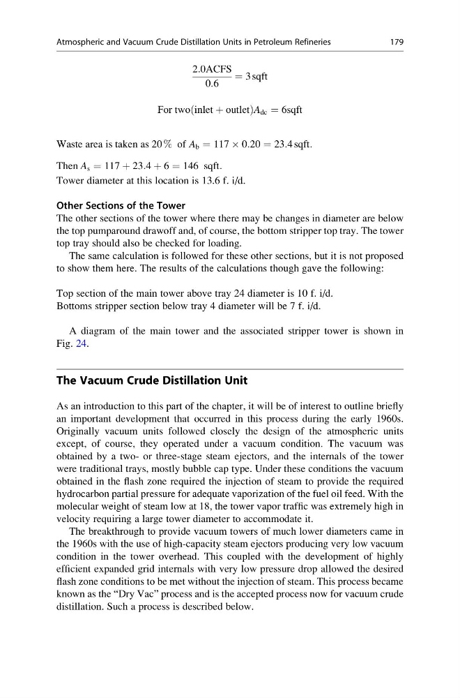
2:0ACFS
0:6
¼ 3 sqft
For two inlet þ outlet
ð
Þ A dc ¼ 6sqft
Waste area is taken as 20 % of A b ¼ 117 Â 0:20 ¼ 23:4 sqft:
Then A s ¼ 117 þ 23:4 þ 6 ¼ 146 sqft:
Tower diameter at this location is 13.6 f. i/d.
Other Sections of the Tower
The other sections of the tower where there may be changes in diameter are below
the top pumparound drawoff and, of course, the bottom stripper top tray. The tower
top tray should also be checked for loading.
The same calculation is followed for these other sections, but it is not proposed
to show them here. The results of the calculations though gave the following:
Top section of the main tower above tray 24 diameter is 10 f. i/d.
Bottoms stripper section below tray 4 diameter will be 7 f. i/d.
A diagram of the main tower and the associated stripper tower is shown in
Fig. 24.
The Vacuum Crude Distillation Unit
As an introduction to this part of the chapter, it will be of interest to outline briefly
an important development that occurred in this process during the early 1960s.
Originally vacuum units followed closely the design of the atmospheric units
except, of course, they operated under a vacuum condition. The vacuum was
obtained by a two- or three-stage steam ejectors, and the internals of the tower
were traditional trays, mostly bubble cap type. Under these conditions the vacuum
obtained in the flash zone required the injection of steam to provide the required
hydrocarbon partial pressure for adequate vaporization of the fuel oil feed. With the
molecular weight of steam low at 18, the tower vapor traffic was extremely high in
velocity requiring a large tower diameter to accommodate it.
The breakthrough to provide vacuum towers of much lower diameters came in
the 1960s with the use of high-capacity steam ejectors producing very low vacuum
condition in the tower overhead. This coupled with the development of highly
efficient expanded grid internals with very low pressure drop allowed the desired
flash zone conditions to be met without the injection of steam. This process became
known as the “Dry Vac” process and is the accepted process now for vacuum crude
distillation. Such a process is described below.
Atmospheric and Vacuum Crude Distillation Units in Petroleum Refineries
179
0:6
¼ 3 sqft
For two inlet þ outlet
ð
Þ A dc ¼ 6sqft
Waste area is taken as 20 % of A b ¼ 117 Â 0:20 ¼ 23:4 sqft:
Then A s ¼ 117 þ 23:4 þ 6 ¼ 146 sqft:
Tower diameter at this location is 13.6 f. i/d.
Other Sections of the Tower
The other sections of the tower where there may be changes in diameter are below
the top pumparound drawoff and, of course, the bottom stripper top tray. The tower
top tray should also be checked for loading.
The same calculation is followed for these other sections, but it is not proposed
to show them here. The results of the calculations though gave the following:
Top section of the main tower above tray 24 diameter is 10 f. i/d.
Bottoms stripper section below tray 4 diameter will be 7 f. i/d.
A diagram of the main tower and the associated stripper tower is shown in
Fig. 24.
The Vacuum Crude Distillation Unit
As an introduction to this part of the chapter, it will be of interest to outline briefly
an important development that occurred in this process during the early 1960s.
Originally vacuum units followed closely the design of the atmospheric units
except, of course, they operated under a vacuum condition. The vacuum was
obtained by a two- or three-stage steam ejectors, and the internals of the tower
were traditional trays, mostly bubble cap type. Under these conditions the vacuum
obtained in the flash zone required the injection of steam to provide the required
hydrocarbon partial pressure for adequate vaporization of the fuel oil feed. With the
molecular weight of steam low at 18, the tower vapor traffic was extremely high in
velocity requiring a large tower diameter to accommodate it.
The breakthrough to provide vacuum towers of much lower diameters came in
the 1960s with the use of high-capacity steam ejectors producing very low vacuum
condition in the tower overhead. This coupled with the development of highly
efficient expanded grid internals with very low pressure drop allowed the desired
flash zone conditions to be met without the injection of steam. This process became
known as the “Dry Vac” process and is the accepted process now for vacuum crude
distillation. Such a process is described below.
Atmospheric and Vacuum Crude Distillation Units in Petroleum Refineries
179