

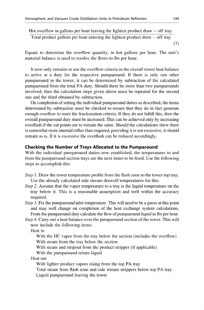
Hot overflow in gallons per hour leaving the lightest product draw À off tray
Total product gallons per hour entering the lightest product draw À off tray
:
(7)
Equate to determine the overflow quantity, in hot gallons per hour. The unit’s
material balance is used to resolve the flows to lbs per hour.
It now only remains to use the overflow criteria in the overall tower heat balance
to arrive at a duty for the respective pumparound. If there is only one other
pumparound in the tower, it can be determined by subtraction of the calculated
pumparound from the total PA duty. Should there be more than two pumparounds
involved, then the calculation steps given above must be repeated for the second
one and the third obtained by subtraction.
On completion of setting the individual pumparound duties as described, the items
determined by subtraction must be checked to ensure that they do in fact generate
enough overflow to meet the fractionation criteria. If they do not fulfill this, then the
overall pumparound duty must be increased. This can be achieved only by increasing
overflash if the cut points are to remain the same. Should the calculations show there
is somewhat more internal reflux than required, providing it is not excessive, it should
remain as is. If it is excessive the overflash can be reduced accordingly.
Checking the Number of Trays Allocated to the Pumparound
With the individual pumparound duties now established, the temperatures to and
from the pumparound section trays are the next items to be fixed. Use the following
steps to accomplish this:
Step 1. Draw the tower temperature profile from the flash zone to the tower top tray.
Use the already calculated side stream drawoff temperatures for this.
Step 2. Assume that the vapor temperature to a tray is the liquid temperature on the
tray below it. This is a reasonable assumption and well within the accuracy
required.
Step 3. Fix the pumparound inlet temperature. This will need to be a guess at this point
and may well change on completion of the heat exchange system calculations.
From the pumparound duty calculate the flow of pumparound liquid in lbs per hour.
Step 4. Carry out a heat balance over the pumparound section of the tower. This will
now include the following items:
Heat in
With the HC vapor from the tray below the section (includes the overflow)
With steam from the tray below the section
With steam and stripout from the product stripper (if applicable)
With the pumparound return liquid
Heat out
With lighter product vapors rising from the top PA tray
Total steam from flash zone and side stream strippers below top PA tray
Liquid pumparound leaving the tower
Atmospheric and Vacuum Crude Distillation Units in Petroleum Refineries
149
Total product gallons per hour entering the lightest product draw À off tray
:
(7)
Equate to determine the overflow quantity, in hot gallons per hour. The unit’s
material balance is used to resolve the flows to lbs per hour.
It now only remains to use the overflow criteria in the overall tower heat balance
to arrive at a duty for the respective pumparound. If there is only one other
pumparound in the tower, it can be determined by subtraction of the calculated
pumparound from the total PA duty. Should there be more than two pumparounds
involved, then the calculation steps given above must be repeated for the second
one and the third obtained by subtraction.
On completion of setting the individual pumparound duties as described, the items
determined by subtraction must be checked to ensure that they do in fact generate
enough overflow to meet the fractionation criteria. If they do not fulfill this, then the
overall pumparound duty must be increased. This can be achieved only by increasing
overflash if the cut points are to remain the same. Should the calculations show there
is somewhat more internal reflux than required, providing it is not excessive, it should
remain as is. If it is excessive the overflash can be reduced accordingly.
Checking the Number of Trays Allocated to the Pumparound
With the individual pumparound duties now established, the temperatures to and
from the pumparound section trays are the next items to be fixed. Use the following
steps to accomplish this:
Step 1. Draw the tower temperature profile from the flash zone to the tower top tray.
Use the already calculated side stream drawoff temperatures for this.
Step 2. Assume that the vapor temperature to a tray is the liquid temperature on the
tray below it. This is a reasonable assumption and well within the accuracy
required.
Step 3. Fix the pumparound inlet temperature. This will need to be a guess at this point
and may well change on completion of the heat exchange system calculations.
From the pumparound duty calculate the flow of pumparound liquid in lbs per hour.
Step 4. Carry out a heat balance over the pumparound section of the tower. This will
now include the following items:
Heat in
With the HC vapor from the tray below the section (includes the overflow)
With steam from the tray below the section
With steam and stripout from the product stripper (if applicable)
With the pumparound return liquid
Heat out
With lighter product vapors rising from the top PA tray
Total steam from flash zone and side stream strippers below top PA tray
Liquid pumparound leaving the tower
Atmospheric and Vacuum Crude Distillation Units in Petroleum Refineries
149