

During a 3D acquisition the source antenna and
receiver antenna will form varying configurations.
When the source- and receiver antennas are in line
with each other the configuration is called inline and
the data collected are inline data. When the antennas
are parallel and perpendicular to each other the
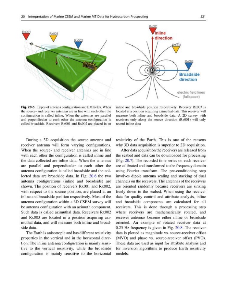
antenna configuration is called broadside and the collected data are broadside data. In Fig. 20.6 the two
antenna configurations (inline and broadside) are
shown. The position of receivers Rx001 and Rx002,
with respect to the source position, are placed at an
inline and broadside position respectively. Most of the
antenna configuration within a 3D CSEM survey will
be antenna configuration with an azimuth component.
Such data is called azimuthal data. Receivers Rx002
and Rx003 are located in a position acquiring azimuthal data, and will measure both inline and broadside data.
The Earth is anisotropic and has different resistivity
properties in the vertical and in the horizontal direction. The inline antenna configuration is mainly sensitive to the vertical resistivity, while the broadside
configuration is mainly sensitive to the horizontal
resistivity of the Earth. This is one of the reasons
why 3D data acquisition is superior to 2D acquisition.
After data acquisition the receivers are released from
the seabed and data can be downloaded for processing
(Fig. 20.7). The recorded time series on each receiver
are calibrated and transformed to the frequency domain
using Fourier transform. The pre-conditioning step
involves dipole antenna scaling and stacking of dual
channels on the receivers. The antennas of the receivers
are oriented randomly because receivers are sinking
freely down to the seabed. When using the receiver
data for quality control and attribute analysis, inline
and broadside components are calculated for all
receivers. This is done through a processing step
where receivers are mathematically rotated, and
receiver antennas become either inline or broadside
oriented. An example of rotated receiver data at
0.25 Hz frequency is given in Fig. 20.8. The receiver
data is plotted as magnitude vs. source-receiver offset
(MVO) and phase vs. source-receiver offset (PVO).
These data are used as input for attribute analysis and
for inversion algorithms to produce Earth resistivity
models.
Fig. 20.6 Types of antenna configuration and EM fields. When
the source- and receiver antennas are in line with each other the
configuration is called inline. When the antennas are parallel
and perpendicular to each other the antenna configuration is
called broadside. Receivers Rx001 and Rx002 are placed in an
inline and broadside position respectively. Receiver Rx003 is
located at a position acquiring azimuthal data. This receiver will
measure both inline and broadside data. A 2D survey with
receivers only along the source direction (Rx001) will only
record inline data
20 Interpretation of Marine CSEM and Marine MT Data for Hydrocarbon Prospecting
521
receiver antenna will form varying configurations.
When the source- and receiver antennas are in line
with each other the configuration is called inline and
the data collected are inline data. When the antennas
are parallel and perpendicular to each other the
antenna configuration is called broadside and the collected data are broadside data. In Fig. 20.6 the two
antenna configurations (inline and broadside) are
shown. The position of receivers Rx001 and Rx002,
with respect to the source position, are placed at an
inline and broadside position respectively. Most of the
antenna configuration within a 3D CSEM survey will
be antenna configuration with an azimuth component.
Such data is called azimuthal data. Receivers Rx002
and Rx003 are located in a position acquiring azimuthal data, and will measure both inline and broadside data.
The Earth is anisotropic and has different resistivity
properties in the vertical and in the horizontal direction. The inline antenna configuration is mainly sensitive to the vertical resistivity, while the broadside
configuration is mainly sensitive to the horizontal
resistivity of the Earth. This is one of the reasons
why 3D data acquisition is superior to 2D acquisition.
After data acquisition the receivers are released from
the seabed and data can be downloaded for processing
(Fig. 20.7). The recorded time series on each receiver
are calibrated and transformed to the frequency domain
using Fourier transform. The pre-conditioning step
involves dipole antenna scaling and stacking of dual
channels on the receivers. The antennas of the receivers
are oriented randomly because receivers are sinking
freely down to the seabed. When using the receiver
data for quality control and attribute analysis, inline
and broadside components are calculated for all
receivers. This is done through a processing step
where receivers are mathematically rotated, and
receiver antennas become either inline or broadside
oriented. An example of rotated receiver data at
0.25 Hz frequency is given in Fig. 20.8. The receiver
data is plotted as magnitude vs. source-receiver offset
(MVO) and phase vs. source-receiver offset (PVO).
These data are used as input for attribute analysis and
for inversion algorithms to produce Earth resistivity
models.
Fig. 20.6 Types of antenna configuration and EM fields. When
the source- and receiver antennas are in line with each other the
configuration is called inline. When the antennas are parallel
and perpendicular to each other the antenna configuration is
called broadside. Receivers Rx001 and Rx002 are placed in an
inline and broadside position respectively. Receiver Rx003 is
located at a position acquiring azimuthal data. This receiver will
measure both inline and broadside data. A 2D survey with
receivers only along the source direction (Rx001) will only
record inline data
20 Interpretation of Marine CSEM and Marine MT Data for Hydrocarbon Prospecting
521