

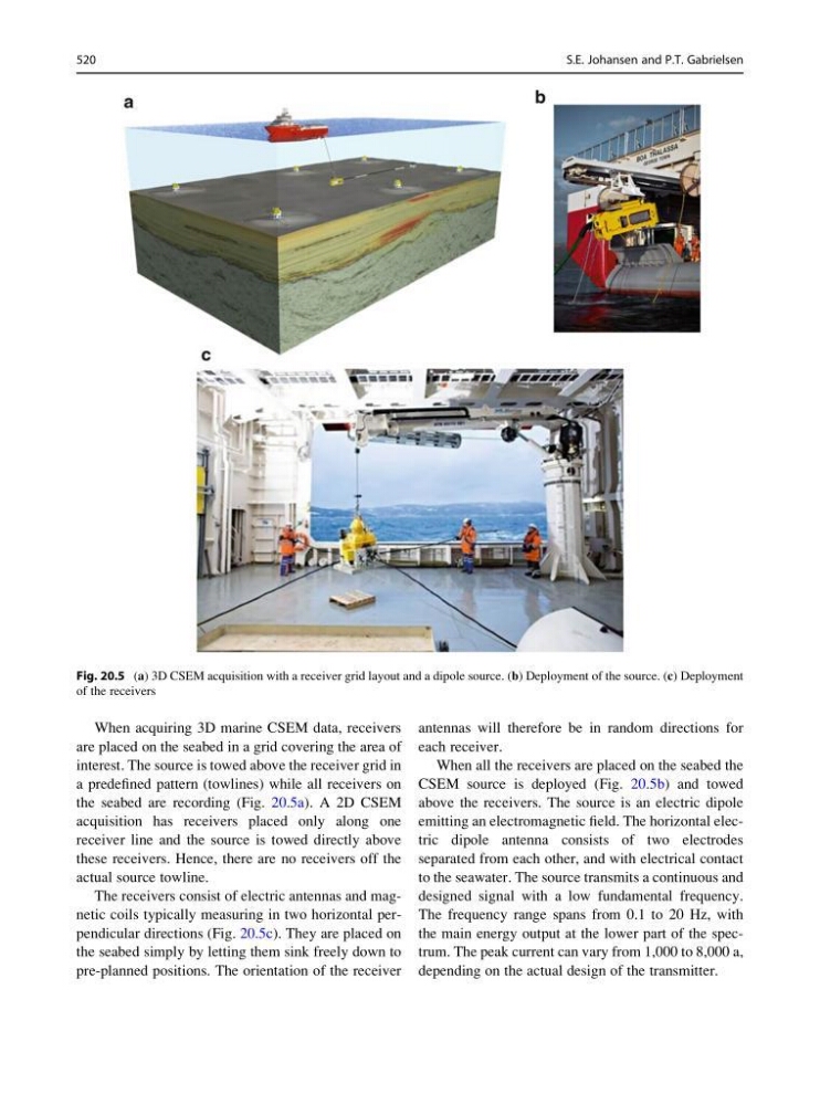
When acquiring 3D marine CSEM data, receivers
are placed on the seabed in a grid covering the area of
interest. The source is towed above the receiver grid in
a predefined pattern (towlines) while all receivers on
the seabed are recording (Fig. 20.5a). A 2D CSEM
acquisition has receivers placed only along one
receiver line and the source is towed directly above
these receivers. Hence, there are no receivers off the
actual source towline.
The receivers consist of electric antennas and magnetic coils typically measuring in two horizontal perpendicular directions (Fig. 20.5c). They are placed on
the seabed simply by letting them sink freely down to
pre-planned positions. The orientation of the receiver
antennas will therefore be in random directions for
each receiver.
When all the receivers are placed on the seabed the
CSEM source is deployed (Fig. 20.5b) and towed
above the receivers. The source is an electric dipole
emitting an electromagnetic field. The horizontal electric dipole antenna consists of two electrodes
separated from each other, and with electrical contact
to the seawater. The source transmits a continuous and
designed signal with a low fundamental frequency.
The frequency range spans from 0.1 to 20 Hz, with
the main energy output at the lower part of the spectrum. The peak current can vary from 1,000 to 8,000 a,
depending on the actual design of the transmitter.
Fig. 20.5 (a) 3D CSEM acquisition with a receiver grid layout and a dipole source. (b) Deployment of the source. (c) Deployment
of the receivers
520
S.E. Johansen and P.T. Gabrielsen
are placed on the seabed in a grid covering the area of
interest. The source is towed above the receiver grid in
a predefined pattern (towlines) while all receivers on
the seabed are recording (Fig. 20.5a). A 2D CSEM
acquisition has receivers placed only along one
receiver line and the source is towed directly above
these receivers. Hence, there are no receivers off the
actual source towline.
The receivers consist of electric antennas and magnetic coils typically measuring in two horizontal perpendicular directions (Fig. 20.5c). They are placed on
the seabed simply by letting them sink freely down to
pre-planned positions. The orientation of the receiver
antennas will therefore be in random directions for
each receiver.
When all the receivers are placed on the seabed the
CSEM source is deployed (Fig. 20.5b) and towed
above the receivers. The source is an electric dipole
emitting an electromagnetic field. The horizontal electric dipole antenna consists of two electrodes
separated from each other, and with electrical contact
to the seawater. The source transmits a continuous and
designed signal with a low fundamental frequency.
The frequency range spans from 0.1 to 20 Hz, with
the main energy output at the lower part of the spectrum. The peak current can vary from 1,000 to 8,000 a,
depending on the actual design of the transmitter.
Fig. 20.5 (a) 3D CSEM acquisition with a receiver grid layout and a dipole source. (b) Deployment of the source. (c) Deployment
of the receivers
520
S.E. Johansen and P.T. Gabrielsen