

Another way is to combine near and far offset travel
time analysis (Landrø and Stammeijer 2004) to estimate velocity and thickness changes simultaneously.
Hatchell et al. and Røste et al. suggested in 2005 using
a factor (R) relating the relative velocity change (dv/v)
to the relative thickness change (dz/z; displacement)
R ¼ À
dv=v
dz=z
(19.9)
Hatchell et al. found that this factor varies between
1 and 5, and is normally less for the reservoir rock than
for the overburden rocks. Laboratory measurements
(Holt et al. 2008 and Bathija et al. 2009) show that
the R-factor strongly depends on the stress state of the
rock and the stress path, and that it typically decreases
with increasing axial stress. For sandstones and clays it
is common to establish empirical relationships
between seismic P-wave velocity (v) and porosity
(ϕ). These relations are often of the simple linear
form:
v ¼ aϕ þ b
(19.10)
where a and b are empirical parameters. If a rock is
stretched (or compressed), a corresponding change in
porosity will occur. It is important to emphasise that
Eq. (19.10) is simplified and does not include changes
in grain contact stiffness or changes in crack density.
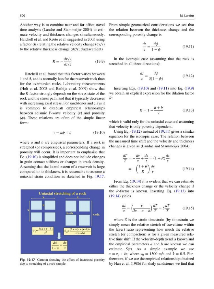
Assuming that the lateral extent of a reservoir is large
compared to its thickness, it is reasonable to assume a
uniaxial strain condition as sketched in Fig. 19.17.
From simple geometrical considerations we see that
the relation between the thickness change and the
corresponding porosity change is:
dz
z
¼
dϕ
1 À ϕ
(19.11)
In the isotropic case (assuming that the rock is
stretched in all three directions):
dz
z
¼
dϕ
3ð1 À ϕÞ
(19.12)
Inserting Eqs. (19.10) and (19.11) into Eq. (19.9)
we obtain an explicit expression for the dilation factor
R:
R ¼ 1 À
a þ b
v
(19.13)
which is valid only for the uniaxial case and assuming
that velocity is only porosity dependent.
Using Eq. (19.12) instead of (19.11) gives a similar
equation for the isotropic case. The relation between
the measured time shift and the velocity and thickness
changes is given as (Landrø and Stammeijer 2004):
dT
T
¼ À
dv
v
þ
dz
z
¼ 1 þ R
ð
Þ
dz
z
¼ À
1 þ R
R
dv
v
(19.14)
From Eq. (19.14) it is evident that we can estimate
either the thickness change or the velocity change if
the R-factor is known. Inserting Eq. (19.13) into
(19.14) yields
dz
z
¼
v
2v À a À b
dT
T
¼ S
dT
T
(19.15)
where S is the strain-timestrain (by timestrain we
simply mean the relative stretch of traveltime within
the layer) ratio representing how much the relative
stretch (or compaction) is for a given measured relative time shift. If the velocity-depth trend is known and
the empirical parameters a and b are known we can
estimate S(z). As a simple example we use
v ¼ v 0 þ kz, where v 0 ¼ 1500 m/s and k ¼ 0.5. Furthermore, if we use the empirical relationship obtained
by Han et al. (1986) for shaly sandstones we find that
Uniaxial stretching of a rock
x
x
h
h(x + x – h)
(h + dx)x + (x – h)h
x(x + dx)
x
2
d
1
2
1 –
=
dx
x
h+dx
x+dx
x
=
=
Fig. 19.17 Cartoon showing the effect of increased porosity
due to stretching of a rock sample
500
M. Landrø
time analysis (Landrø and Stammeijer 2004) to estimate velocity and thickness changes simultaneously.
Hatchell et al. and Røste et al. suggested in 2005 using
a factor (R) relating the relative velocity change (dv/v)
to the relative thickness change (dz/z; displacement)
R ¼ À
dv=v
dz=z
(19.9)
Hatchell et al. found that this factor varies between
1 and 5, and is normally less for the reservoir rock than
for the overburden rocks. Laboratory measurements
(Holt et al. 2008 and Bathija et al. 2009) show that
the R-factor strongly depends on the stress state of the
rock and the stress path, and that it typically decreases
with increasing axial stress. For sandstones and clays it
is common to establish empirical relationships
between seismic P-wave velocity (v) and porosity
(ϕ). These relations are often of the simple linear
form:
v ¼ aϕ þ b
(19.10)
where a and b are empirical parameters. If a rock is
stretched (or compressed), a corresponding change in
porosity will occur. It is important to emphasise that
Eq. (19.10) is simplified and does not include changes
in grain contact stiffness or changes in crack density.
Assuming that the lateral extent of a reservoir is large
compared to its thickness, it is reasonable to assume a
uniaxial strain condition as sketched in Fig. 19.17.
From simple geometrical considerations we see that
the relation between the thickness change and the
corresponding porosity change is:
dz
z
¼
dϕ
1 À ϕ
(19.11)
In the isotropic case (assuming that the rock is
stretched in all three directions):
dz
z
¼
dϕ
3ð1 À ϕÞ
(19.12)
Inserting Eqs. (19.10) and (19.11) into Eq. (19.9)
we obtain an explicit expression for the dilation factor
R:
R ¼ 1 À
a þ b
v
(19.13)
which is valid only for the uniaxial case and assuming
that velocity is only porosity dependent.
Using Eq. (19.12) instead of (19.11) gives a similar
equation for the isotropic case. The relation between
the measured time shift and the velocity and thickness
changes is given as (Landrø and Stammeijer 2004):
dT
T
¼ À
dv
v
þ
dz
z
¼ 1 þ R
ð
Þ
dz
z
¼ À
1 þ R
R
dv
v
(19.14)
From Eq. (19.14) it is evident that we can estimate
either the thickness change or the velocity change if
the R-factor is known. Inserting Eq. (19.13) into
(19.14) yields
dz
z
¼
v
2v À a À b
dT
T
¼ S
dT
T
(19.15)
where S is the strain-timestrain (by timestrain we
simply mean the relative stretch of traveltime within
the layer) ratio representing how much the relative
stretch (or compaction) is for a given measured relative time shift. If the velocity-depth trend is known and
the empirical parameters a and b are known we can
estimate S(z). As a simple example we use
v ¼ v 0 þ kz, where v 0 ¼ 1500 m/s and k ¼ 0.5. Furthermore, if we use the empirical relationship obtained
by Han et al. (1986) for shaly sandstones we find that
Uniaxial stretching of a rock
x
x
h
h(x + x – h)
(h + dx)x + (x – h)h
x(x + dx)
x
2
d
1
2
1 –
=
dx
x
h+dx
x+dx
x
=
=
Fig. 19.17 Cartoon showing the effect of increased porosity
due to stretching of a rock sample
500
M. Landrø