

wave is being reflected from the top and the bottom of
a bed, the result will depend on the interaction of
closely spaced pulses. In order for two nearby reflective interfaces to be distinguished well, they have to be
about λ/4 in thickness which is called the tuning thickness. This is also the thickness where interpretation
criteria change. For smaller thickness, the limit of
visibility is reached and positional uncertainties are
introduced.
The typical recorded seismic frequencies are in the
range of 5–100 Hz. High frequency and short
wavelengths provide better vertical and lateral resolution. One could argue that we could simply increase
the power of our source so that high frequencies
could travel farther without being attenuated. However, there is a practical limitation in generating high
frequencies that can penetrate large depths. The Earth
acts as a natural filter removing the higher
frequencies more readily than the lower frequencies
(absorption effect). This means the deeper the source
of reflections, the lower the frequencies we can
receive from those depths and therefore the lower
resolution we appear to have from great depths
(Fig. 17.28). The vertical resolution decreases with
the distance travelled (hence depth) by the ray
because attenuation preferentially robs the signal of
the higher frequency components. Deconvolution can
improve vertical resolution by producing a broad
bandwidth with high frequencies and a relatively
compressed wavelet.
Fig. 17.26 A comparison of Pre-stack time migrated (top) and Post-stack depth migrated (bottom) images
A
A ′
Z
S
Z
+
λ
/4
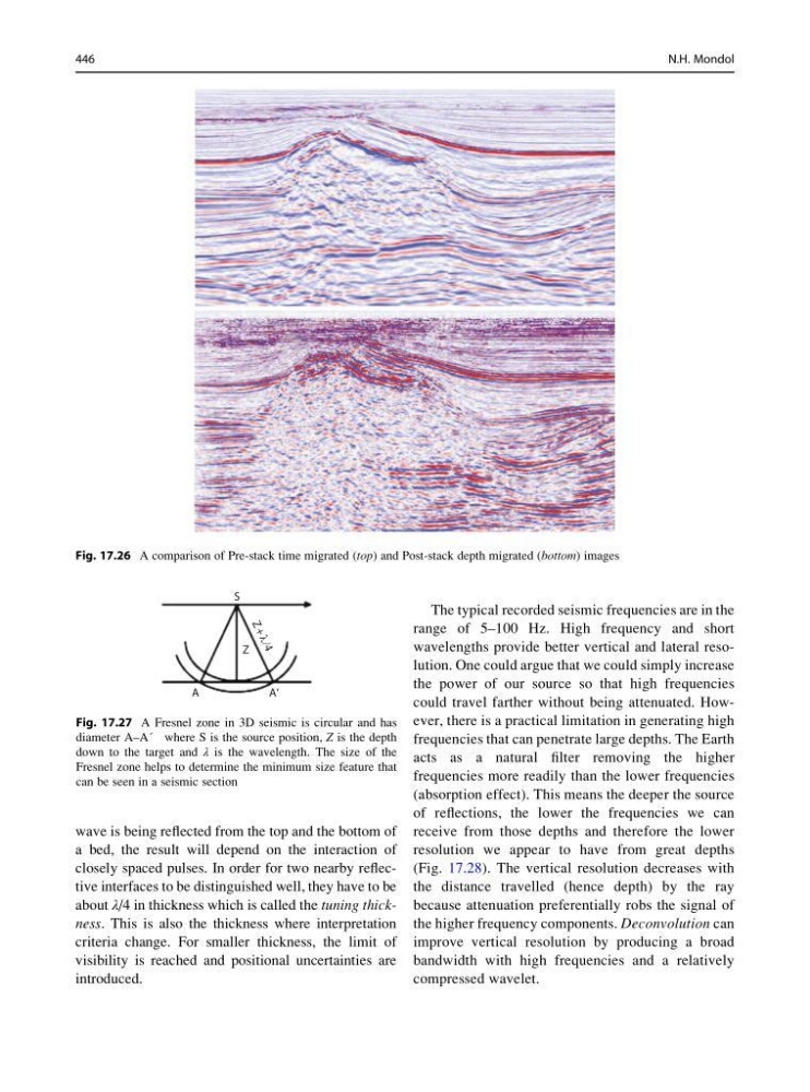
Fig. 17.27 A Fresnel zone in 3D seismic is circular and has
diameter A–A´ where S is the source position, Z is the depth
down to the target and λ is the wavelength. The size of the
Fresnel zone helps to determine the minimum size feature that
can be seen in a seismic section
446
N.H. Mondol
a bed, the result will depend on the interaction of
closely spaced pulses. In order for two nearby reflective interfaces to be distinguished well, they have to be
about λ/4 in thickness which is called the tuning thickness. This is also the thickness where interpretation
criteria change. For smaller thickness, the limit of
visibility is reached and positional uncertainties are
introduced.
The typical recorded seismic frequencies are in the
range of 5–100 Hz. High frequency and short
wavelengths provide better vertical and lateral resolution. One could argue that we could simply increase
the power of our source so that high frequencies
could travel farther without being attenuated. However, there is a practical limitation in generating high
frequencies that can penetrate large depths. The Earth
acts as a natural filter removing the higher
frequencies more readily than the lower frequencies
(absorption effect). This means the deeper the source
of reflections, the lower the frequencies we can
receive from those depths and therefore the lower
resolution we appear to have from great depths
(Fig. 17.28). The vertical resolution decreases with
the distance travelled (hence depth) by the ray
because attenuation preferentially robs the signal of
the higher frequency components. Deconvolution can
improve vertical resolution by producing a broad
bandwidth with high frequencies and a relatively
compressed wavelet.
Fig. 17.26 A comparison of Pre-stack time migrated (top) and Post-stack depth migrated (bottom) images
A
A ′
Z
S
Z
+
λ
/4
Fig. 17.27 A Fresnel zone in 3D seismic is circular and has
diameter A–A´ where S is the source position, Z is the depth
down to the target and λ is the wavelength. The size of the
Fresnel zone helps to determine the minimum size feature that
can be seen in a seismic section
446
N.H. Mondol