

depends on a good velocity analysis. In the case of an
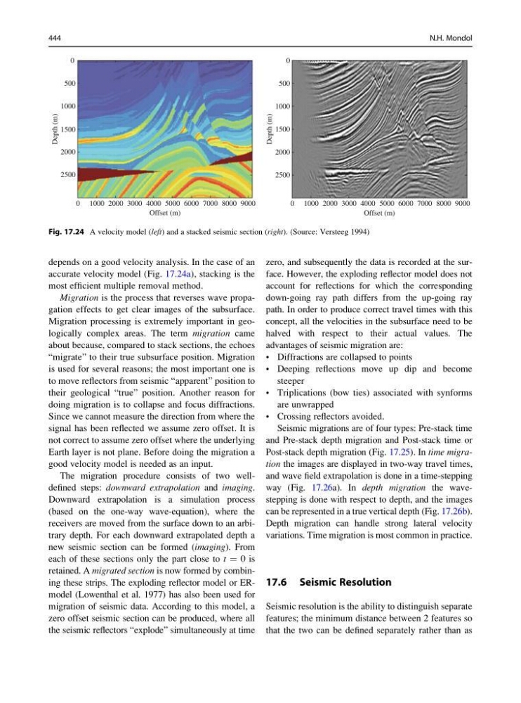
accurate velocity model (Fig. 17.24a), stacking is the
most efficient multiple removal method.
Migration is the process that reverses wave propagation effects to get clear images of the subsurface.
Migration processing is extremely important in geologically complex areas. The term migration came
about because, compared to stack sections, the echoes
“migrate” to their true subsurface position. Migration
is used for several reasons; the most important one is
to move reflectors from seismic “apparent” position to
their geological “true” position. Another reason for
doing migration is to collapse and focus diffractions.
Since we cannot measure the direction from where the
signal has been reflected we assume zero offset. It is
not correct to assume zero offset where the underlying
Earth layer is not plane. Before doing the migration a
good velocity model is needed as an input.
The migration procedure consists of two welldefined steps: downward extrapolation and imaging.
Downward extrapolation is a simulation process
(based on the one-way wave-equation), where the
receivers are moved from the surface down to an arbitrary depth. For each downward extrapolated depth a
new seismic section can be formed (imaging). From
each of these sections only the part close to t ¼ 0 is
retained. A migrated section is now formed by combining these strips. The exploding reflector model or ERmodel (Lowenthal et al. 1977) has also been used for
migration of seismic data. According to this model, a
zero offset seismic section can be produced, where all
the seismic reflectors “explode” simultaneously at time
zero, and subsequently the data is recorded at the surface. However, the exploding reflector model does not
account for reflections for which the corresponding
down-going ray path differs from the up-going ray
path. In order to produce correct travel times with this
concept, all the velocities in the subsurface need to be
halved with respect to their actual values. The
advantages of seismic migration are:
• Diffractions are collapsed to points
• Deeping reflections move up dip and become
steeper
• Triplications (bow ties) associated with synforms
are unwrapped
• Crossing reflectors avoided.
Seismic migrations are of four types: Pre-stack time
and Pre-stack depth migration and Post-stack time or
Post-stack depth migration (Fig. 17.25). In time migration the images are displayed in two-way travel times,
and wave field extrapolation is done in a time-stepping
way (Fig. 17.26a). In depth migration the wavestepping is done with respect to depth, and the images
can be represented in a true vertical depth (Fig. 17.26b).
Depth migration can handle strong lateral velocity
variations. Time migration is most common in practice.
17.6 Seismic Resolution
Seismic resolution is the ability to distinguish separate
features; the minimum distance between 2 features so
that the two can be defined separately rather than as
2500
0 1000 2000 3000 4000 5000
Offset (m)
6000 7000 8000 9000
2000
Depth (m)
1500
1000
500
0
2500
0 1000 2000 3000 4000 5000
Offset (m)
6000 7000 8000 9000
2000
Depth (m)
1500
1000
500
0
Fig. 17.24 A velocity model (left) and a stacked seismic section (right). (Source: Versteeg 1994)
444
N.H. Mondol
accurate velocity model (Fig. 17.24a), stacking is the
most efficient multiple removal method.
Migration is the process that reverses wave propagation effects to get clear images of the subsurface.
Migration processing is extremely important in geologically complex areas. The term migration came
about because, compared to stack sections, the echoes
“migrate” to their true subsurface position. Migration
is used for several reasons; the most important one is
to move reflectors from seismic “apparent” position to
their geological “true” position. Another reason for
doing migration is to collapse and focus diffractions.
Since we cannot measure the direction from where the
signal has been reflected we assume zero offset. It is
not correct to assume zero offset where the underlying
Earth layer is not plane. Before doing the migration a
good velocity model is needed as an input.
The migration procedure consists of two welldefined steps: downward extrapolation and imaging.
Downward extrapolation is a simulation process
(based on the one-way wave-equation), where the
receivers are moved from the surface down to an arbitrary depth. For each downward extrapolated depth a
new seismic section can be formed (imaging). From
each of these sections only the part close to t ¼ 0 is
retained. A migrated section is now formed by combining these strips. The exploding reflector model or ERmodel (Lowenthal et al. 1977) has also been used for
migration of seismic data. According to this model, a
zero offset seismic section can be produced, where all
the seismic reflectors “explode” simultaneously at time
zero, and subsequently the data is recorded at the surface. However, the exploding reflector model does not
account for reflections for which the corresponding
down-going ray path differs from the up-going ray
path. In order to produce correct travel times with this
concept, all the velocities in the subsurface need to be
halved with respect to their actual values. The
advantages of seismic migration are:
• Diffractions are collapsed to points
• Deeping reflections move up dip and become
steeper
• Triplications (bow ties) associated with synforms
are unwrapped
• Crossing reflectors avoided.
Seismic migrations are of four types: Pre-stack time
and Pre-stack depth migration and Post-stack time or
Post-stack depth migration (Fig. 17.25). In time migration the images are displayed in two-way travel times,
and wave field extrapolation is done in a time-stepping
way (Fig. 17.26a). In depth migration the wavestepping is done with respect to depth, and the images
can be represented in a true vertical depth (Fig. 17.26b).
Depth migration can handle strong lateral velocity
variations. Time migration is most common in practice.
17.6 Seismic Resolution
Seismic resolution is the ability to distinguish separate
features; the minimum distance between 2 features so
that the two can be defined separately rather than as
2500
0 1000 2000 3000 4000 5000
Offset (m)
6000 7000 8000 9000
2000
Depth (m)
1500
1000
500
0
2500
0 1000 2000 3000 4000 5000
Offset (m)
6000 7000 8000 9000
2000
Depth (m)
1500
1000
500
0
Fig. 17.24 A velocity model (left) and a stacked seismic section (right). (Source: Versteeg 1994)
444
N.H. Mondol