

resultant image represents only a section below the
line. Unfortunately, this method does not always produce a clear subsurface image. 2D data can often be
distorted with diffractions and events produced from
offline geologic structures, making accurate interpretation difficult. Because seismic waves travel along
expanding wavefronts they have a surface area. A
truly representative image of the subsurface is only
obtained when the entire wavefield is sampled.
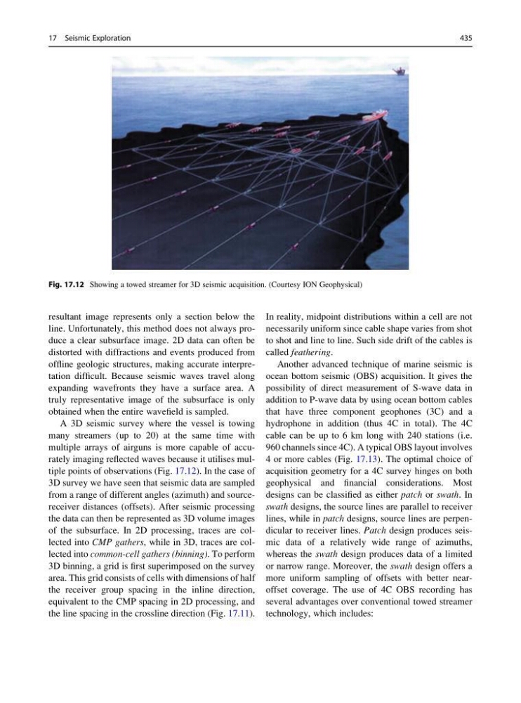
A 3D seismic survey where the vessel is towing
many streamers (up to 20) at the same time with
multiple arrays of airguns is more capable of accurately imaging reflected waves because it utilises multiple points of observations (Fig. 17.12). In the case of
3D survey we have seen that seismic data are sampled
from a range of different angles (azimuth) and sourcereceiver distances (offsets). After seismic processing
the data can then be represented as 3D volume images
of the subsurface. In 2D processing, traces are collected into CMP gathers, while in 3D, traces are collected into common-cell gathers (binning). To perform
3D binning, a grid is first superimposed on the survey
area. This grid consists of cells with dimensions of half
the receiver group spacing in the inline direction,
equivalent to the CMP spacing in 2D processing, and
the line spacing in the crossline direction (Fig. 17.11).
In reality, midpoint distributions within a cell are not
necessarily uniform since cable shape varies from shot
to shot and line to line. Such side drift of the cables is
called feathering.
Another advanced technique of marine seismic is
ocean bottom seismic (OBS) acquisition. It gives the
possibility of direct measurement of S-wave data in
addition to P-wave data by using ocean bottom cables
that have three component geophones (3C) and a
hydrophone in addition (thus 4C in total). The 4C
cable can be up to 6 km long with 240 stations (i.e.
960 channels since 4C). A typical OBS layout involves
4 or more cables (Fig. 17.13). The optimal choice of
acquisition geometry for a 4C survey hinges on both
geophysical and financial considerations. Most
designs can be classified as either patch or swath. In
swath designs, the source lines are parallel to receiver
lines, while in patch designs, source lines are perpendicular to receiver lines. Patch design produces seismic data of a relatively wide range of azimuths,
whereas the swath design produces data of a limited
or narrow range. Moreover, the swath design offers a
more uniform sampling of offsets with better nearoffset coverage. The use of 4C OBS recording has
several advantages over conventional towed streamer
technology, which includes:
Fig. 17.12 Showing a towed streamer for 3D seismic acquisition. (Courtesy ION Geophysical)
17 Seismic Exploration
435
line. Unfortunately, this method does not always produce a clear subsurface image. 2D data can often be
distorted with diffractions and events produced from
offline geologic structures, making accurate interpretation difficult. Because seismic waves travel along
expanding wavefronts they have a surface area. A
truly representative image of the subsurface is only
obtained when the entire wavefield is sampled.
A 3D seismic survey where the vessel is towing
many streamers (up to 20) at the same time with
multiple arrays of airguns is more capable of accurately imaging reflected waves because it utilises multiple points of observations (Fig. 17.12). In the case of
3D survey we have seen that seismic data are sampled
from a range of different angles (azimuth) and sourcereceiver distances (offsets). After seismic processing
the data can then be represented as 3D volume images
of the subsurface. In 2D processing, traces are collected into CMP gathers, while in 3D, traces are collected into common-cell gathers (binning). To perform
3D binning, a grid is first superimposed on the survey
area. This grid consists of cells with dimensions of half
the receiver group spacing in the inline direction,
equivalent to the CMP spacing in 2D processing, and
the line spacing in the crossline direction (Fig. 17.11).
In reality, midpoint distributions within a cell are not
necessarily uniform since cable shape varies from shot
to shot and line to line. Such side drift of the cables is
called feathering.
Another advanced technique of marine seismic is
ocean bottom seismic (OBS) acquisition. It gives the
possibility of direct measurement of S-wave data in
addition to P-wave data by using ocean bottom cables
that have three component geophones (3C) and a
hydrophone in addition (thus 4C in total). The 4C
cable can be up to 6 km long with 240 stations (i.e.
960 channels since 4C). A typical OBS layout involves
4 or more cables (Fig. 17.13). The optimal choice of
acquisition geometry for a 4C survey hinges on both
geophysical and financial considerations. Most
designs can be classified as either patch or swath. In
swath designs, the source lines are parallel to receiver
lines, while in patch designs, source lines are perpendicular to receiver lines. Patch design produces seismic data of a relatively wide range of azimuths,
whereas the swath design produces data of a limited
or narrow range. Moreover, the swath design offers a
more uniform sampling of offsets with better nearoffset coverage. The use of 4C OBS recording has
several advantages over conventional towed streamer
technology, which includes:
Fig. 17.12 Showing a towed streamer for 3D seismic acquisition. (Courtesy ION Geophysical)
17 Seismic Exploration
435