

hydrophones, which respond to changes in water pressure. In marine acquisition, seismic vessels sail along
predetermined patterns of parallel circuits
(Fig. 17.11). The length of straight segments is calculated from fold plots, and must include additional
length – run in and run out – to allow the cable to
straighten after each turn. Marine seismic acquisition
is faster than conventional land seismic because it does
not require jug hustlers to lay and pick up geophones
(Rygg et al. 1992).
The advance to 3D seismic acquisition and imaging
of the subsurface, introduced in the 1980s, was perhaps the most important step in seismic exploration
(Beckett et al. 1995). The 3D seismic images began to
resolve the detailed subsurface structural and stratigraphic conditions that were missing or not
discernable from 2D seismic data. With 3D seismic
acquisition potential reservoirs are imaged in three
dimensions, which allows seismic interpreters to
view the data in cross-sections along 360
of azimuth,
in depth slices parallel to the ground surface, and along
planes that cut arbitrarily through the data volume.
Information such as faulting and fracturing, bedding
plane direction, the presence of pore fluids, complex
geological structure, and detailed stratigraphy are now
commonly interpreted from 3D seismic data sets.
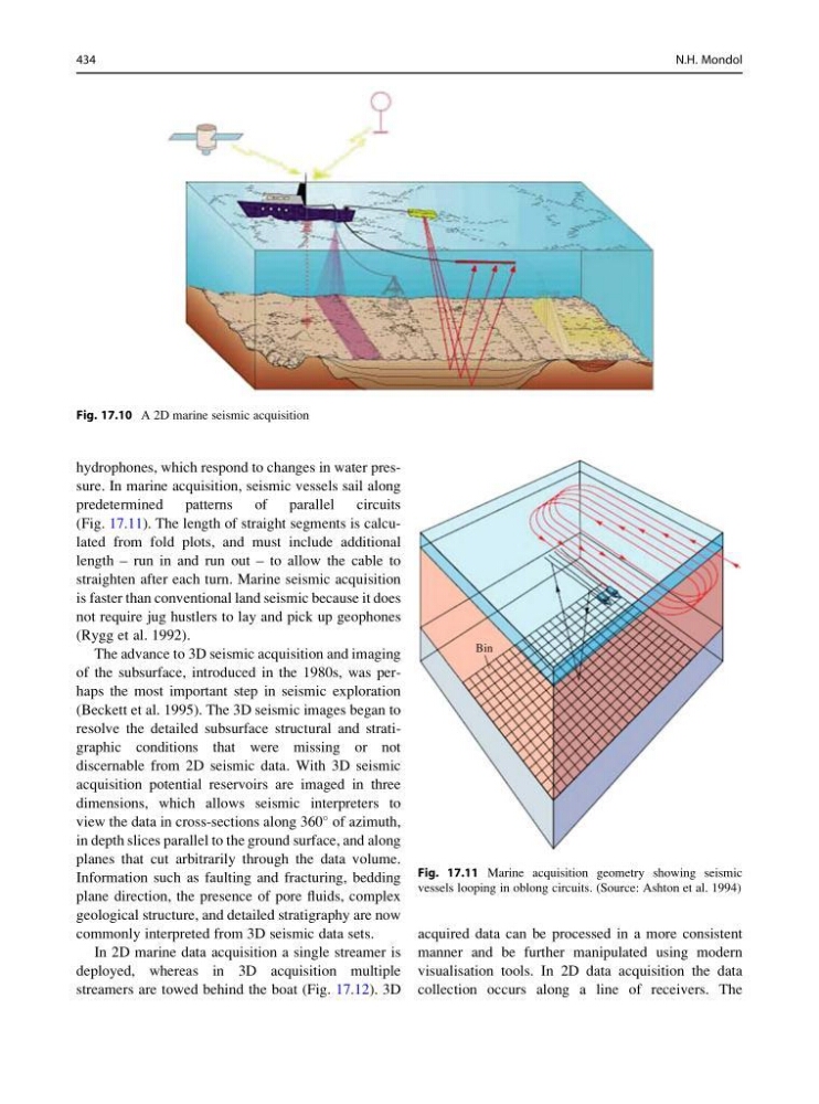
In 2D marine data acquisition a single streamer is
deployed, whereas in 3D acquisition multiple
streamers are towed behind the boat (Fig. 17.12). 3D
acquired data can be processed in a more consistent
manner and be further manipulated using modern
visualisation tools. In 2D data acquisition the data
collection occurs along a line of receivers. The
Fig. 17.10 A 2D marine seismic acquisition
Bin
Fig. 17.11 Marine acquisition geometry showing seismic
vessels looping in oblong circuits. (Source: Ashton et al. 1994)
434
N.H. Mondol
predetermined patterns of parallel circuits
(Fig. 17.11). The length of straight segments is calculated from fold plots, and must include additional
length – run in and run out – to allow the cable to
straighten after each turn. Marine seismic acquisition
is faster than conventional land seismic because it does
not require jug hustlers to lay and pick up geophones
(Rygg et al. 1992).
The advance to 3D seismic acquisition and imaging
of the subsurface, introduced in the 1980s, was perhaps the most important step in seismic exploration
(Beckett et al. 1995). The 3D seismic images began to
resolve the detailed subsurface structural and stratigraphic conditions that were missing or not
discernable from 2D seismic data. With 3D seismic
acquisition potential reservoirs are imaged in three
dimensions, which allows seismic interpreters to
view the data in cross-sections along 360
of azimuth,
in depth slices parallel to the ground surface, and along
planes that cut arbitrarily through the data volume.
Information such as faulting and fracturing, bedding
plane direction, the presence of pore fluids, complex
geological structure, and detailed stratigraphy are now
commonly interpreted from 3D seismic data sets.
In 2D marine data acquisition a single streamer is
deployed, whereas in 3D acquisition multiple
streamers are towed behind the boat (Fig. 17.12). 3D
acquired data can be processed in a more consistent
manner and be further manipulated using modern
visualisation tools. In 2D data acquisition the data
collection occurs along a line of receivers. The
Fig. 17.10 A 2D marine seismic acquisition
Bin
Fig. 17.11 Marine acquisition geometry showing seismic
vessels looping in oblong circuits. (Source: Ashton et al. 1994)
434
N.H. Mondol