

times of waves returning to the surface after being
reflected or refracted from the interface(s) of one or
more layers. When a seismic source emits a pulse that
propagates through the sedimentary layers, the sound
waves travel between the layers with different velocities
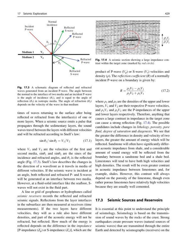
and will be refracted according to Snell’s law:
sin θ 1 = sin θ 2 ¼ V 1 =V 2
(17.1)
where V 1 and V 2 are the velocities of the first and
second media, sinθ 1 and sinθ 2 are the sines of the
incidence and refracted angles, and θ 3 is the reflected
angle (Fig. 17.3). Snell’s law describes the changes in
the direction of a wavefront as it travels in media of
different velocities. If the seismic wave is incident at
an angle, both reflected and refracted P- and S-waves
will be generated at an interface between two media.
However, at a fluid-solid interface like the seafloor, Swaves will not exist in the fluid part.
A line or grid of geophones or hydrophones called
seismic receivers records the reflected and refracted
seismic signals. Reflections from the layer interfaces
in the subsurface are then measured at receivers (time
measurements). If the two layers have different
velocities, they will as a rule also have different
densities, and part of the acoustic energy will not be
refracted, but reflected. How much of the energy is
reflected depends on the difference in the impedance
[P-impedance (Z p ) or S-impedance (Z s )], which are the
product of P-wave (V p ) or S-wave (V s ) velocities and
density (ρ). The reflection coefficient (R) of a normally
incident P-wave on a boundary is given by:
R ¼
ρ 2 V 2 À ρ 1 V 1
ρ 2 V 2 þ ρ 1 V 1
(17.2)
where ρ 1 and ρ 2 are the densities of the upper and lower
layers, V 1 and V 2 are their respective P-wave velocities,
and ρ 1 V 1 and ρ 2 V 2 are the P-impedances of the upper
and lower layers respectively. Therefore, anything that
causes a large contrast in impedance in the target zone
can cause a strong reflection (Fig. 17.4). The possible
candidates include changes in lithology, porosity, pore
fluid, degree of saturation and diagenesis. We see that
the greater the difference in density and velocity of two
layers, the greater the amount of energy which will be
reflected. Sandstone will often have significantly different acoustic impedance from shale, and a considerable
amount of sound energy will be reflected from the
boundary between a sandstone bed and a shale bed.
Limestones will tend to have both high velocities and
high densities. The result will be even greater contrast
in acoustic impedance between limestones and, for
example, shales. However, this contrast will always
depend on the porosity of the limestone, though even
rather porous limestones have relatively high velocities
because they are usually well cemented.
17.3 Seismic Sources and Reservoirs
It is essential at this point to understand the principle
of seismology. Seismology is based on the transmission of sound waves by the rocks of the crust. Strong
earthquakes create pressure waves (natural sources of
seismic waves) that are transmitted through the entire
Earth and detected by seismographs (receivers) on the
Normal
incidence
Incident
P-wave
Reflected
S-wave
Reflected
P-wave
θ 1
θ 3
θ 2
V 1
V 2
Medium 1
Medium 2
Refracted
P-wave
Refracted
S-wave
Fig. 17.3 A schematic diagram of reflected and refracted
waves generated from an incident P-wave. The angle between
the normal to the interface of two media and an incident P-wave
is the angle of incidence (θ 1 ), and is equal to the angle of
reflection (θ 3 ) in isotropic media. The angle of refraction (θ 2 )
depends on the velocity of the wave in that medium
ρ 1 V 1
ρ 2 V 2
–
Fig. 17.4 A seismic section showing a large impedance contrast within the target zone (marked by red circle)
17 Seismic Exploration
429
reflected or refracted from the interface(s) of one or
more layers. When a seismic source emits a pulse that
propagates through the sedimentary layers, the sound
waves travel between the layers with different velocities
and will be refracted according to Snell’s law:
sin θ 1 = sin θ 2 ¼ V 1 =V 2
(17.1)
where V 1 and V 2 are the velocities of the first and
second media, sinθ 1 and sinθ 2 are the sines of the
incidence and refracted angles, and θ 3 is the reflected
angle (Fig. 17.3). Snell’s law describes the changes in
the direction of a wavefront as it travels in media of
different velocities. If the seismic wave is incident at
an angle, both reflected and refracted P- and S-waves
will be generated at an interface between two media.
However, at a fluid-solid interface like the seafloor, Swaves will not exist in the fluid part.
A line or grid of geophones or hydrophones called
seismic receivers records the reflected and refracted
seismic signals. Reflections from the layer interfaces
in the subsurface are then measured at receivers (time
measurements). If the two layers have different
velocities, they will as a rule also have different
densities, and part of the acoustic energy will not be
refracted, but reflected. How much of the energy is
reflected depends on the difference in the impedance
[P-impedance (Z p ) or S-impedance (Z s )], which are the
product of P-wave (V p ) or S-wave (V s ) velocities and
density (ρ). The reflection coefficient (R) of a normally
incident P-wave on a boundary is given by:
R ¼
ρ 2 V 2 À ρ 1 V 1
ρ 2 V 2 þ ρ 1 V 1
(17.2)
where ρ 1 and ρ 2 are the densities of the upper and lower
layers, V 1 and V 2 are their respective P-wave velocities,
and ρ 1 V 1 and ρ 2 V 2 are the P-impedances of the upper
and lower layers respectively. Therefore, anything that
causes a large contrast in impedance in the target zone
can cause a strong reflection (Fig. 17.4). The possible
candidates include changes in lithology, porosity, pore
fluid, degree of saturation and diagenesis. We see that
the greater the difference in density and velocity of two
layers, the greater the amount of energy which will be
reflected. Sandstone will often have significantly different acoustic impedance from shale, and a considerable
amount of sound energy will be reflected from the
boundary between a sandstone bed and a shale bed.
Limestones will tend to have both high velocities and
high densities. The result will be even greater contrast
in acoustic impedance between limestones and, for
example, shales. However, this contrast will always
depend on the porosity of the limestone, though even
rather porous limestones have relatively high velocities
because they are usually well cemented.
17.3 Seismic Sources and Reservoirs
It is essential at this point to understand the principle
of seismology. Seismology is based on the transmission of sound waves by the rocks of the crust. Strong
earthquakes create pressure waves (natural sources of
seismic waves) that are transmitted through the entire
Earth and detected by seismographs (receivers) on the
Normal
incidence
Incident
P-wave
Reflected
S-wave
Reflected
P-wave
θ 1
θ 3
θ 2
V 1
V 2
Medium 1
Medium 2
Refracted
P-wave
Refracted
S-wave
Fig. 17.3 A schematic diagram of reflected and refracted
waves generated from an incident P-wave. The angle between
the normal to the interface of two media and an incident P-wave
is the angle of incidence (θ 1 ), and is equal to the angle of
reflection (θ 3 ) in isotropic media. The angle of refraction (θ 2 )
depends on the velocity of the wave in that medium
ρ 1 V 1
ρ 2 V 2
–
Fig. 17.4 A seismic section showing a large impedance contrast within the target zone (marked by red circle)
17 Seismic Exploration
429