

• Estimation of mudcake thickness, h mc ¼ (d bit – d h )/
2, where h stands for the hole, in inches.
• Measurement of borehole volume, V h ¼ (d h
2 /
2) + 1.2%, in litres per metre.
• Measurement of required cement volume, V cement
¼ 0.5 Â (d h
2 – d
2
casing ) + 1%, in litres per metre.
• Selection of consolidated formations for wireline
pressure tests, recovery of fluid samples, and for
packer seating for well testing purposes.
16.5.2.3 Uncertainties of Caliper Log
Known challenges with caliper logging include borehole spiralling. The position of the drill bit may precess as it drills, leading to spiraling shapes in the
wellbore wall, as if the hole had been drilled by a
screw. If the arms of the caliper log follow the grooves
of the spiral, it will report too high an average diameter. Moving in and out of the grooves, the caliper will
give erratic or periodically varying readings. In most
cases, the borehole’s circumference will not be a perfect circle and therefore a caliper tool with several
arms is required to obtain a true understanding of the
size and shape of the borehole. The borehole can
change to an oval shape after drilling, which can
cause the caliper log to overestimate the size of the
borehole.
16.5.3 Self-Potential/Spontaneous
Potential (SP) Log
16.5.3.1 Generalities and Basic Principles
The self-potential/spontaneous potential log (SP) was
the first wireline logging tool used in hydrocarbon
exploration. It is very simple, requiring only an electrode in the borehole and a reference electrode at the
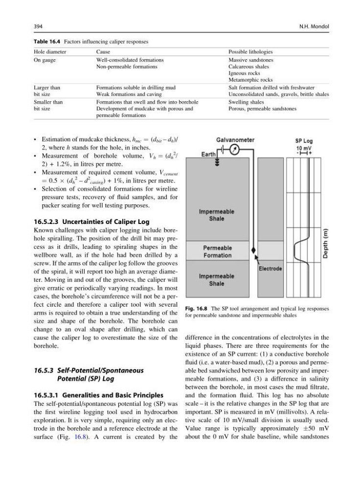
surface (Fig. 16.8). A current is created by the
difference in the concentrations of electrolytes in the
liquid phases. There are three requirements for the
existence of an SP current: (1) a conductive borehole
fluid (i.e. a water-based mud), (2) a porous and permeable bed sandwiched between low porosity and impermeable formations, and (3) a difference in salinity
between the borehole, in most cases the mud filtrate,
and the formation fluid. This log has no absolute
scale – it is the relative changes in the SP log that are
important. SP is measured in mV (millivolts). A relative scale of 10 mV/small division is usually used.
Value range is typically approximately Æ50 mV
about the 0 mV for shale baseline, while sandstones
Fig. 16.8 The SP tool arrangement and typical log responses
for permeable sandstone and impermeable shales
Table 16.4 Factors influencing caliper responses
Hole diameter
Cause
Possible lithologies
On gauge
Well-consolidated formations
Non-permeable formations
Massive sandstones
Calcareous shales
Igneous rocks
Metamorphic rocks
Larger than
bit size
Formations soluble in drilling mud
Weak formations and caving
Salt formation drilled with freshwater
Unconsolidated sands, gravels, brittle shales
Smaller than
bit size
Formations that swell and flow into borehole
Development of mudcake with porous and
permeable formations
Swelling shales
Porous, permeable sandstones
394
N.H. Mondol
2, where h stands for the hole, in inches.
• Measurement of borehole volume, V h ¼ (d h
2 /
2) + 1.2%, in litres per metre.
• Measurement of required cement volume, V cement
¼ 0.5 Â (d h
2 – d
2
casing ) + 1%, in litres per metre.
• Selection of consolidated formations for wireline
pressure tests, recovery of fluid samples, and for
packer seating for well testing purposes.
16.5.2.3 Uncertainties of Caliper Log
Known challenges with caliper logging include borehole spiralling. The position of the drill bit may precess as it drills, leading to spiraling shapes in the
wellbore wall, as if the hole had been drilled by a
screw. If the arms of the caliper log follow the grooves
of the spiral, it will report too high an average diameter. Moving in and out of the grooves, the caliper will
give erratic or periodically varying readings. In most
cases, the borehole’s circumference will not be a perfect circle and therefore a caliper tool with several
arms is required to obtain a true understanding of the
size and shape of the borehole. The borehole can
change to an oval shape after drilling, which can
cause the caliper log to overestimate the size of the
borehole.
16.5.3 Self-Potential/Spontaneous
Potential (SP) Log
16.5.3.1 Generalities and Basic Principles
The self-potential/spontaneous potential log (SP) was
the first wireline logging tool used in hydrocarbon
exploration. It is very simple, requiring only an electrode in the borehole and a reference electrode at the
surface (Fig. 16.8). A current is created by the
difference in the concentrations of electrolytes in the
liquid phases. There are three requirements for the
existence of an SP current: (1) a conductive borehole
fluid (i.e. a water-based mud), (2) a porous and permeable bed sandwiched between low porosity and impermeable formations, and (3) a difference in salinity
between the borehole, in most cases the mud filtrate,
and the formation fluid. This log has no absolute
scale – it is the relative changes in the SP log that are
important. SP is measured in mV (millivolts). A relative scale of 10 mV/small division is usually used.
Value range is typically approximately Æ50 mV
about the 0 mV for shale baseline, while sandstones
Fig. 16.8 The SP tool arrangement and typical log responses
for permeable sandstone and impermeable shales
Table 16.4 Factors influencing caliper responses
Hole diameter
Cause
Possible lithologies
On gauge
Well-consolidated formations
Non-permeable formations
Massive sandstones
Calcareous shales
Igneous rocks
Metamorphic rocks
Larger than
bit size
Formations soluble in drilling mud
Weak formations and caving
Salt formation drilled with freshwater
Unconsolidated sands, gravels, brittle shales
Smaller than
bit size
Formations that swell and flow into borehole
Development of mudcake with porous and
permeable formations
Swelling shales
Porous, permeable sandstones
394
N.H. Mondol