

492
Stratigraphic and Tectonic Controls on the Distribution and Architecture of Fluvial OU and Gas Reservoirs
structure. The large fields of the North Viking Graben (e.g., Kirk 1980; Parsley 1984; Sect. 15.3.3) and
the North Slope of Alaska (Morgridge and Smith
1972; Wadman et a!. 1979; Bloch eta!. 1990; Fig. 14.8;
Sect. 15.3.1) include good examples of SH-type reservoirs, as does Messla field, Libya (Clifford et a!. 1980;
Sect. 15.3.2). All these are located in extensionalmargin tectonic settings, the North Viking Graben
being a major rift structure. The Hutton Sandstone
of Erornanga Basin, Australia, forms the reservoir in
many structurally trapped SH-type fields. The basin
is a foreland basin, but the sandstone was derived
from structural upwa.rps on the cratonic side of
the basin (Moore et a!. 1986; Watts 1987; john and
Almond 1987; Wecker 1989).
These fields require a structural trapping mechanism because, by definition, the reservoir consists of
a sheetlike porous unit providing little or no constraints on fluid movement. Most of the cases referred to here consist of large faulted anticlines
in which the reservoir sandstone is overlain by an
impermeable shale. The Hassi Messaoud field of
Algeria produces from a breached anticline, in which
the reservoir sandstone has heen eroded from the
crest·of the anticline (Balducchi and Pommier 1970).
A different type of structural SH-type field is
exemplified by Red Earth field, Alberta, which produces from the basal Paleozoic Granite Wash sand�
stone. The reservoir is a sheetlike unit, and the trap is
provided by drape over paleotopographic highs, reflecting the original erosional topography that was
covered by Granite Wash sedimentation (Hunter
1966).
The detailed geological and engineering information required for production modeling may result in
the definition of considerable internal heterogeneity
within reservoir bodies that, at an early exploration
stage, might appear fairly uniform. Fields that are
originally classified as SH type might later be better
considered CB type, at least in terms of the style of
research required to further develop them. The considerable amount of production modeling carried
out on the braided "sheet'' of the Sadlerochit Formation at Prudhoe Bay field (Wadman et a!. 1979;
Geehan et a!. 1986; Atkinson et a!. 1990), the
Kekiktnk Formation of Endicott field (Woidneck et
a!. 1987; Melvin 1993), and the Statfjord Formation
of Statfjord field (MacDonald and Halland 1993;
Martin 1993) are good examples. Recent studies,
particularly of North Sea fields, have stimulated a
considerable body of work in the area of computer
modeling of fluvjal systems and comparisons with
outcrop analogs (e.g., Buller et a!. 1990; Mia!! and
Tyler 1991; Ashton 1992; Flint and )3ryant 1993; Martin 1993), the details of which are beyond the scope of
this chapter ($orne aspects are dis�ussed in Sect.
10.4.3). Similarly, developments in the use of 3-D
seismic mapping for channel definition are proceeding at a rapid pace (e.g., A.R. Brown 1991; D .. Brown
1993; Weber 1993). Techniques of" surveillance geology", including pressure tests and fluid-flow monitoring, may prove to be extremely powerful tools for
subsurface mapping as field development proceeds
(Sect. 9.5.9).
14.4.3 Channel-and-Bar Bodies (CB Type)
CB-type fields are characterized by the small size of
the individual reservoir body, although in some
cases there may be hundreds to thousands of individual reservoir units which, if all filled with petroleum (as they are in some cases), can add up to
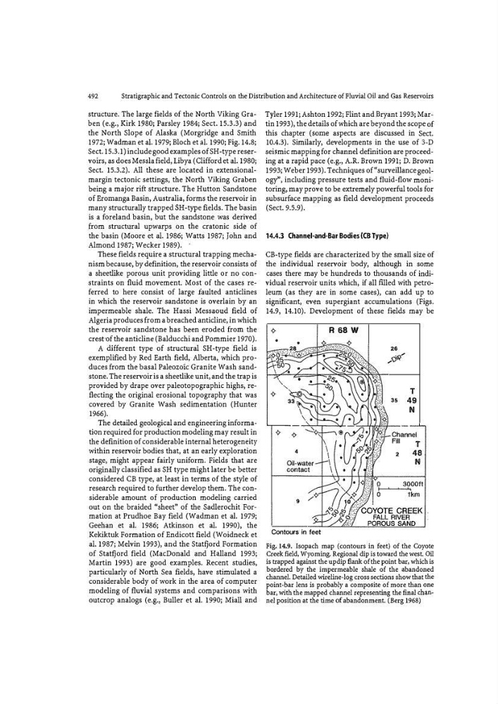
significant, ev�n supergiant accumulations (Figs.
14.9, 14.10). Development of these fields may be
•
9
Contours in feet
R 68 W
T
35 49
N
Fig.14.9. Isopach map (contours in feet) of the Coyote
Creek field, Wyoming. Regional dip is toward the west. Oil
is trapped against the up dip flank of the point bar, which is
bo. rdered by the impermeable shale of the abandoned
channel. Detailed wireline-log cross sections show that the
point-bar lens is probably a composite of more than one
bar, with the mapped channel representing the final chan�
nel position at the time of abandonment. (Berg 1968)
Stratigraphic and Tectonic Controls on the Distribution and Architecture of Fluvial OU and Gas Reservoirs
structure. The large fields of the North Viking Graben (e.g., Kirk 1980; Parsley 1984; Sect. 15.3.3) and
the North Slope of Alaska (Morgridge and Smith
1972; Wadman et a!. 1979; Bloch eta!. 1990; Fig. 14.8;
Sect. 15.3.1) include good examples of SH-type reservoirs, as does Messla field, Libya (Clifford et a!. 1980;
Sect. 15.3.2). All these are located in extensionalmargin tectonic settings, the North Viking Graben
being a major rift structure. The Hutton Sandstone
of Erornanga Basin, Australia, forms the reservoir in
many structurally trapped SH-type fields. The basin
is a foreland basin, but the sandstone was derived
from structural upwa.rps on the cratonic side of
the basin (Moore et a!. 1986; Watts 1987; john and
Almond 1987; Wecker 1989).
These fields require a structural trapping mechanism because, by definition, the reservoir consists of
a sheetlike porous unit providing little or no constraints on fluid movement. Most of the cases referred to here consist of large faulted anticlines
in which the reservoir sandstone is overlain by an
impermeable shale. The Hassi Messaoud field of
Algeria produces from a breached anticline, in which
the reservoir sandstone has heen eroded from the
crest·of the anticline (Balducchi and Pommier 1970).
A different type of structural SH-type field is
exemplified by Red Earth field, Alberta, which produces from the basal Paleozoic Granite Wash sand�
stone. The reservoir is a sheetlike unit, and the trap is
provided by drape over paleotopographic highs, reflecting the original erosional topography that was
covered by Granite Wash sedimentation (Hunter
1966).
The detailed geological and engineering information required for production modeling may result in
the definition of considerable internal heterogeneity
within reservoir bodies that, at an early exploration
stage, might appear fairly uniform. Fields that are
originally classified as SH type might later be better
considered CB type, at least in terms of the style of
research required to further develop them. The considerable amount of production modeling carried
out on the braided "sheet'' of the Sadlerochit Formation at Prudhoe Bay field (Wadman et a!. 1979;
Geehan et a!. 1986; Atkinson et a!. 1990), the
Kekiktnk Formation of Endicott field (Woidneck et
a!. 1987; Melvin 1993), and the Statfjord Formation
of Statfjord field (MacDonald and Halland 1993;
Martin 1993) are good examples. Recent studies,
particularly of North Sea fields, have stimulated a
considerable body of work in the area of computer
modeling of fluvjal systems and comparisons with
outcrop analogs (e.g., Buller et a!. 1990; Mia!! and
Tyler 1991; Ashton 1992; Flint and )3ryant 1993; Martin 1993), the details of which are beyond the scope of
this chapter ($orne aspects are dis�ussed in Sect.
10.4.3). Similarly, developments in the use of 3-D
seismic mapping for channel definition are proceeding at a rapid pace (e.g., A.R. Brown 1991; D .. Brown
1993; Weber 1993). Techniques of" surveillance geology", including pressure tests and fluid-flow monitoring, may prove to be extremely powerful tools for
subsurface mapping as field development proceeds
(Sect. 9.5.9).
14.4.3 Channel-and-Bar Bodies (CB Type)
CB-type fields are characterized by the small size of
the individual reservoir body, although in some
cases there may be hundreds to thousands of individual reservoir units which, if all filled with petroleum (as they are in some cases), can add up to
significant, ev�n supergiant accumulations (Figs.
14.9, 14.10). Development of these fields may be
•
9
Contours in feet
R 68 W
T
35 49
N
Fig.14.9. Isopach map (contours in feet) of the Coyote
Creek field, Wyoming. Regional dip is toward the west. Oil
is trapped against the up dip flank of the point bar, which is
bo. rdered by the impermeable shale of the abandoned
channel. Detailed wireline-log cross sections show that the
point-bar lens is probably a composite of more than one
bar, with the mapped channel representing the final chan�
nel position at the time of abandonment. (Berg 1968)