

490
Stratigraphic and Tectonic Controls on the Distribution and Architecture of Fluvial Oil and Gas Reservoirs
map. Fine-grained meandering and anastomosing
systems are commonly of this type.
14.4.1 Paleovalley Bodies (PV Type)
Paleovalley bodies are distinguished by the ribbon or
sho e string shape of the reservoir and by their association with regional unconformities. The reservoirs
are typically tens of kilometers in length, up to a few
kilometers in width) and several tens of meters in
thickness (Sect. 15.2). In Ordos basin incised valleys
up to 300 m deep have been mapped (Moore et al.
1986; Song Guochu !988). Paleovalleys define the
former courses of incised meander belts and may be
vit:tually straight) or more or less sino us (e.g., Harms
1966; Weimer 1986). The fill may be entirely fluvial,
1km
contours in m.
A
O.Skm
G = gamma ray log
D = density log
•
.
.
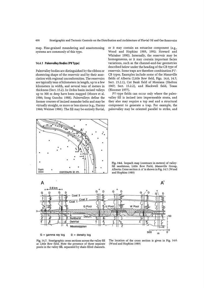
Fig. 14.7. Stratigraphic cross sections across the valley flU
at Little Bow field. Note the presence of three separate
pools in the valley fill , separated by shale-filled channels.
or it may contain an estuarine component (e.g.,
Wood and Hopkins 1989, 1992; Howard and
Whitaker 1990). Internally, the reservoir may be
homogeneous, or it may contain important facies
variations, such as the channel-and-bar geometries
described below under the heading of the CB type of
reservoir. Some traps are therefore combination PVCB types. Examples include some of the Mannville
fields of Alberta (Little Bow field, Figs. 14.6, 14.7;
Sect. 15.2.1), Cut Bank field of Montana (Shelton
1967; Sect. 15.2.2), and Blackwell field, Texas
(Bloomer 1977).
PV -type fields can occur only where the paleovalley fill is incised into impermeable strata, and
they also may require a top seal and a structural
component to generate a trap. For example, the
paleovalley may be oriented parallel to strike, and
Fig.14.6. Isopach map (contours in meters) of valleyfill sandstone, Little Bow Field, Mannville Group,
Alberta. Cross section A-A' is shown in Fig. 14.7. (Wood
and Hopkins 1989)
A'
m
The location of the cross section is given in Fig. 14.6.
(Wood and Hopkins 1989)
Stratigraphic and Tectonic Controls on the Distribution and Architecture of Fluvial Oil and Gas Reservoirs
map. Fine-grained meandering and anastomosing
systems are commonly of this type.
14.4.1 Paleovalley Bodies (PV Type)
Paleovalley bodies are distinguished by the ribbon or
sho e string shape of the reservoir and by their association with regional unconformities. The reservoirs
are typically tens of kilometers in length, up to a few
kilometers in width) and several tens of meters in
thickness (Sect. 15.2). In Ordos basin incised valleys
up to 300 m deep have been mapped (Moore et al.
1986; Song Guochu !988). Paleovalleys define the
former courses of incised meander belts and may be
vit:tually straight) or more or less sino us (e.g., Harms
1966; Weimer 1986). The fill may be entirely fluvial,
1km
contours in m.
A
O.Skm
G = gamma ray log
D = density log
•
.
.
Fig. 14.7. Stratigraphic cross sections across the valley flU
at Little Bow field. Note the presence of three separate
pools in the valley fill , separated by shale-filled channels.
or it may contain an estuarine component (e.g.,
Wood and Hopkins 1989, 1992; Howard and
Whitaker 1990). Internally, the reservoir may be
homogeneous, or it may contain important facies
variations, such as the channel-and-bar geometries
described below under the heading of the CB type of
reservoir. Some traps are therefore combination PVCB types. Examples include some of the Mannville
fields of Alberta (Little Bow field, Figs. 14.6, 14.7;
Sect. 15.2.1), Cut Bank field of Montana (Shelton
1967; Sect. 15.2.2), and Blackwell field, Texas
(Bloomer 1977).
PV -type fields can occur only where the paleovalley fill is incised into impermeable strata, and
they also may require a top seal and a structural
component to generate a trap. For example, the
paleovalley may be oriented parallel to strike, and
Fig.14.6. Isopach map (contours in meters) of valleyfill sandstone, Little Bow Field, Mannville Group,
Alberta. Cross section A-A' is shown in Fig. 14.7. (Wood
and Hopkins 1989)
A'
m
The location of the cross section is given in Fig. 14.6.
(Wood and Hopkins 1989)