

Main Components of the Fluvial Sequence Model
dence for short-term, irregular or pulsed subsidence
driven by thrust-sheet loading, and for rapid uplift
and erosional unroofing, is now abundant (see Sect.
11.4.6).
We are beginning to realize that more than one
process may control sequence development. These
processes can act over different time scales and may
vary in importance from source area to shoreline.
The result can be a complex stratigraphy. This is
exemplified by the Castlegate Sandstone of Utah,
which is one of the units discussed in the following
sections.
13.3 Main Components
of the Fluvial Sequence Model
This discussion uses the standard sequence terminology, as set out by Vail (1987) and Van Wagoner
et a!. (1987) and as emended by Hunt and Tucker
(1992). Their definition of sequences, including the
placement of sequence boundaries at subaerial erosion surfaces fo rmed during base-level lowstand, is
preferred to that of Galloway (1989a), who recommended use of the maximum flooding surface as the
sequence boundary. However, this latter work contains many important ideas and concepts that are
discussed later in this chapter, and in at least one
recent study (Gibling and Bird 1994) it was found
easier to follow Galloway's approach to the definition of sequences, because of the difficulty of
correlating sequence boundaries associated with
discontinuous paleovalley fi lls [a difficulty anticipated by Galloway (1989a)]. Reference is made here
to the two main sequence models for fluvial deposits
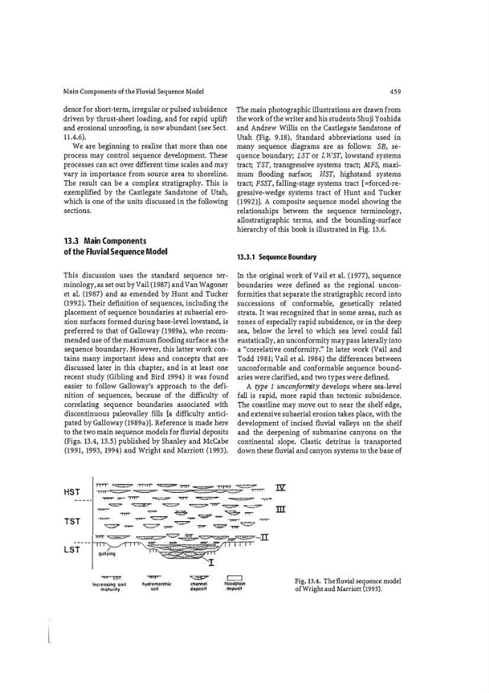
(Figs. 13.4, 13.5) published by Shanley and McCabe
(1991, 1993, 1994) and Wright and Marriott (1993).
459
The main photographic illustrations are drawn from
the work of the writer and his students Shuji Yoshida
and Andrew Willis on the Castlegate Sandstone of
Utah (Fig. 9.18). Standard abbreviations used in
many sequence diagrams are as fo llows: SB, sequence boundary; LST or L WST, lowstand systems
tract; TST, transgressive systems tract; MFS, maximum flooding surface; HST, highstand systems
tract; FSST, falling-stage systems tract [ =forcedMregressive-wedge systems tract of Hunt and Tucker
(1992)]. A composite sequence model showing the
relationships between the sequence terminology,
allostratigraphic terms, and the bounding-surface
hierarchy of this book is illustrated in Fig. 13.6.
13.3.1 Sequence Boundary
In the original work of Vail et a!. (1977), sequence
boundaries were defined as the regional unconfo rmities that separate the stratigraphic record into
successions of conformable, genetically related
strata. It was recognized that in some areas, such as
zones of especially rapid subsidence, or in the deep
sea, below the level to which sea level could fall
eustatically, an unconformity may pass laterally into
a «correlative conformity." In later work (Vail and
Todd 1981; Vail et a!. 1984) the differences between
unconformable and conformable sequence boundaries were clarified, and two types were defined.
A type 1 unconfo rmity develops where sea-level
fall is rapid, more rapid than tectonic subsidence.
The coastline may move out to near the shelf edge,
and extensive subaerial erosion takes place, with the
development of incised fluvial valleys on the shelf
and the deepening of submarine canyons on the
continental slope. Clastic detritus is transported
down these fluvial and canyon systems to the base of
HST
nor � TTTT"T" � Tf11T -=-- TTTTIT �
"'T1T1"'"" ��
�
"T""'T" ""
TST
LST
"'TTT'T" .... .- - "TTT T"'
�
'TITT
�
.... .. .. .: ::=
"'"'1T""'"
"=!:>'
�
�
� ..,.,.,.- � �
"'TT'fT'"
,.,... .. .
�
��
,.,... .. .. . �
....,. .,. .. � .,.,.,... ..
��
� .,.,... .. .
� � �-:::.- �
-=-mr
Increasing soil
maturity
.,hydromorphic
soil
�
channel
deposit
=
floodplain
deposit
m
Fig. 13.4. The fluvial sequence model
of Wright and Marriott (1993}.
dence for short-term, irregular or pulsed subsidence
driven by thrust-sheet loading, and for rapid uplift
and erosional unroofing, is now abundant (see Sect.
11.4.6).
We are beginning to realize that more than one
process may control sequence development. These
processes can act over different time scales and may
vary in importance from source area to shoreline.
The result can be a complex stratigraphy. This is
exemplified by the Castlegate Sandstone of Utah,
which is one of the units discussed in the following
sections.
13.3 Main Components
of the Fluvial Sequence Model
This discussion uses the standard sequence terminology, as set out by Vail (1987) and Van Wagoner
et a!. (1987) and as emended by Hunt and Tucker
(1992). Their definition of sequences, including the
placement of sequence boundaries at subaerial erosion surfaces fo rmed during base-level lowstand, is
preferred to that of Galloway (1989a), who recommended use of the maximum flooding surface as the
sequence boundary. However, this latter work contains many important ideas and concepts that are
discussed later in this chapter, and in at least one
recent study (Gibling and Bird 1994) it was found
easier to follow Galloway's approach to the definition of sequences, because of the difficulty of
correlating sequence boundaries associated with
discontinuous paleovalley fi lls [a difficulty anticipated by Galloway (1989a)]. Reference is made here
to the two main sequence models for fluvial deposits
(Figs. 13.4, 13.5) published by Shanley and McCabe
(1991, 1993, 1994) and Wright and Marriott (1993).
459
The main photographic illustrations are drawn from
the work of the writer and his students Shuji Yoshida
and Andrew Willis on the Castlegate Sandstone of
Utah (Fig. 9.18). Standard abbreviations used in
many sequence diagrams are as fo llows: SB, sequence boundary; LST or L WST, lowstand systems
tract; TST, transgressive systems tract; MFS, maximum flooding surface; HST, highstand systems
tract; FSST, falling-stage systems tract [ =forcedMregressive-wedge systems tract of Hunt and Tucker
(1992)]. A composite sequence model showing the
relationships between the sequence terminology,
allostratigraphic terms, and the bounding-surface
hierarchy of this book is illustrated in Fig. 13.6.
13.3.1 Sequence Boundary
In the original work of Vail et a!. (1977), sequence
boundaries were defined as the regional unconfo rmities that separate the stratigraphic record into
successions of conformable, genetically related
strata. It was recognized that in some areas, such as
zones of especially rapid subsidence, or in the deep
sea, below the level to which sea level could fall
eustatically, an unconformity may pass laterally into
a «correlative conformity." In later work (Vail and
Todd 1981; Vail et a!. 1984) the differences between
unconformable and conformable sequence boundaries were clarified, and two types were defined.
A type 1 unconfo rmity develops where sea-level
fall is rapid, more rapid than tectonic subsidence.
The coastline may move out to near the shelf edge,
and extensive subaerial erosion takes place, with the
development of incised fluvial valleys on the shelf
and the deepening of submarine canyons on the
continental slope. Clastic detritus is transported
down these fluvial and canyon systems to the base of
HST
nor � TTTT"T" � Tf11T -=-- TTTTIT �
"'T1T1"'"" ��
�
"T""'T" ""
TST
LST
"'TTT'T" .... .- - "TTT T"'
�
'TITT
�
.... .. .. .: ::=
"'"'1T""'"
"=!:>'
�
�
� ..,.,.,.- � �
"'TT'fT'"
,.,... .. .
�
��
,.,... .. .. . �
....,. .,. .. � .,.,.,... ..
��
� .,.,... .. .
� � �-:::.- �
-=-mr
Increasing soil
maturity
.,hydromorphic
soil
�
channel
deposit
=
floodplain
deposit
m
Fig. 13.4. The fluvial sequence model
of Wright and Marriott (1993}.