

Metho ds of Correlation and Mapping
SURFACE
CLIFF
FACE
V. E.=1.4
liNE S
Une 1
Line 2
·Surface
Une 3
Una 4
---- - } ·These lines (f rom diagram above ) represent surfaces correlated
with those in other radar sections
·Represents surfaces that could not be COITelated
PROFILE 2
Point bar or mid-channel bar
�lll' 'iltw1c� tr -<::
Position of 3·0 block diagram
DA • Downstream accreting macrofonn
Fig. 9.53B
, ... I
k.
, ---- -
237
Orientation of c!iff-faoa
295
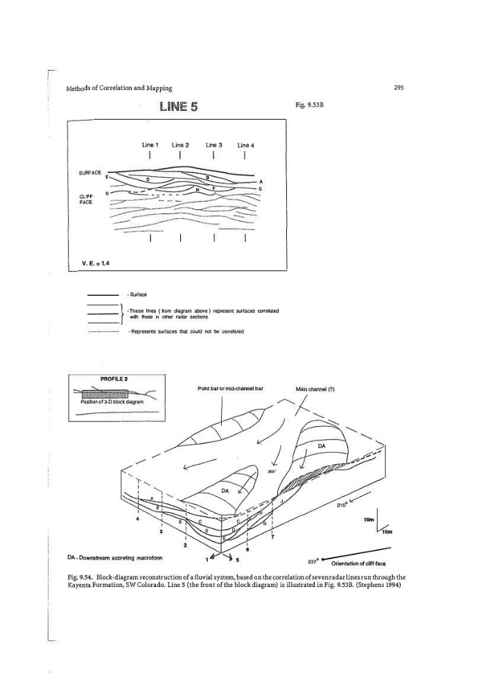
Fig. 9.54. Block-diagram reconstruction of a fluvial system, based on the correlation of seven radar lines run through the
Kayenta Formation, SW Colorado. Line 5 (the front of the block diagram) is illustrated in Fig. 9.53B. (Stephens 1994)
SURFACE
CLIFF
FACE
V. E.=1.4
liNE S
Une 1
Line 2
·Surface
Une 3
Una 4
---- - } ·These lines (f rom diagram above ) represent surfaces correlated
with those in other radar sections
·Represents surfaces that could not be COITelated
PROFILE 2
Point bar or mid-channel bar
�lll' 'iltw1c� tr -<::
Position of 3·0 block diagram
DA • Downstream accreting macrofonn
Fig. 9.53B
, ... I
k.
, ---- -
237
Orientation of c!iff-faoa
295
Fig. 9.54. Block-diagram reconstruction of a fluvial system, based on the correlation of seven radar lines run through the
Kayenta Formation, SW Colorado. Line 5 (the front of the block diagram) is illustrated in Fig. 9.53B. (Stephens 1994)