

Methods of Correlation and Mapping
ray deflection from the edge of the Morrow channel.
All these anomalies may be used to locate actual
chan nels. An actual sesimic line through this area is
reproduced as Fig. 9.50. Note the ('sagging" of the
Marmaton, the ('faults" in the Arbuckle, and the
stron g positive reflection from the channel itself.
Other examples of channel and paleovalley mapping include those by Wood and Hopkins (1989),
who illustrated a seismic section across a Mannville
paleovalley fill in the Little Bow area of Alberta.
Here, the differential compaction of the valley fill
relative to the host strata provided the key for the
identification and mapping of the channels.
Sonnenberg (1987) mapped paleovalleys in the "D"
sandstone of the Denver Basin using techniques
291
similar to those described above for the Morrow
channels.
Many of the stratigraphic traps discussed later in
this book, especially the CB-type fields, are characterized by structural drape over a laterally limited
sandstone ribbon or lens (Chaps. 14, 15). Potentially,
these small structural anomalies can be mapped using refined seismic techniques, once the acoustic
properties of the rocks in question have been thoroughly investigated by regional seismic mapping
and the use of well logs for velocity control.
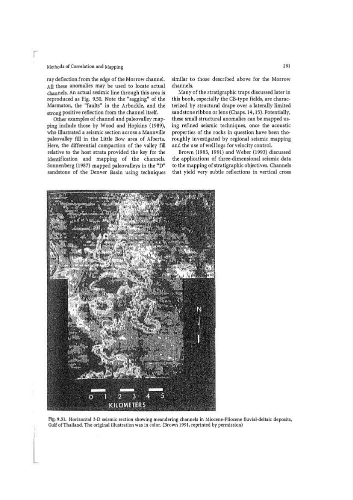
Brown (1985, 1991) and Weber (1993) discussed
the applications of three-dimensional seismic data
to the mapping of stratigraphic objectives. Channels
that yield very subtle reflections in vertical cross
Fig. 9.51. Horizontal 3�D seismic section showing meandering channels in Miocene-Pliocene fluvial-deltaic deposits,
Gulf of Thailand. The original illustration was in color. (Brown 1991> reprinted by permission)
ray deflection from the edge of the Morrow channel.
All these anomalies may be used to locate actual
chan nels. An actual sesimic line through this area is
reproduced as Fig. 9.50. Note the ('sagging" of the
Marmaton, the ('faults" in the Arbuckle, and the
stron g positive reflection from the channel itself.
Other examples of channel and paleovalley mapping include those by Wood and Hopkins (1989),
who illustrated a seismic section across a Mannville
paleovalley fill in the Little Bow area of Alberta.
Here, the differential compaction of the valley fill
relative to the host strata provided the key for the
identification and mapping of the channels.
Sonnenberg (1987) mapped paleovalleys in the "D"
sandstone of the Denver Basin using techniques
291
similar to those described above for the Morrow
channels.
Many of the stratigraphic traps discussed later in
this book, especially the CB-type fields, are characterized by structural drape over a laterally limited
sandstone ribbon or lens (Chaps. 14, 15). Potentially,
these small structural anomalies can be mapped using refined seismic techniques, once the acoustic
properties of the rocks in question have been thoroughly investigated by regional seismic mapping
and the use of well logs for velocity control.
Brown (1985, 1991) and Weber (1993) discussed
the applications of three-dimensional seismic data
to the mapping of stratigraphic objectives. Channels
that yield very subtle reflections in vertical cross
Fig. 9.51. Horizontal 3�D seismic section showing meandering channels in Miocene-Pliocene fluvial-deltaic deposits,
Gulf of Thailand. The original illustration was in color. (Brown 1991> reprinted by permission)