

290
o'
1,000 '
2,000'
3,000'
The Stratigraphic Architecture of Fluvial Depositional Systems
r
1,0,0 0'
2,0,00 ' 3,000' 4,o oo' s.o,oo'
0'
17,000' /SEC
11600'/
1,000'
MARMATON Jl
C •
SEC
MORROW") c 14,900'/SEC 16, 600'/SEC
$MISS!i§li§A N%4 4
� � '
·
AA
1 1,800' I SEC 1 8,400' /SEC
OO'
ARBUCKLE
g LIMESTONE
m SANDSTONE
1m! SHALE
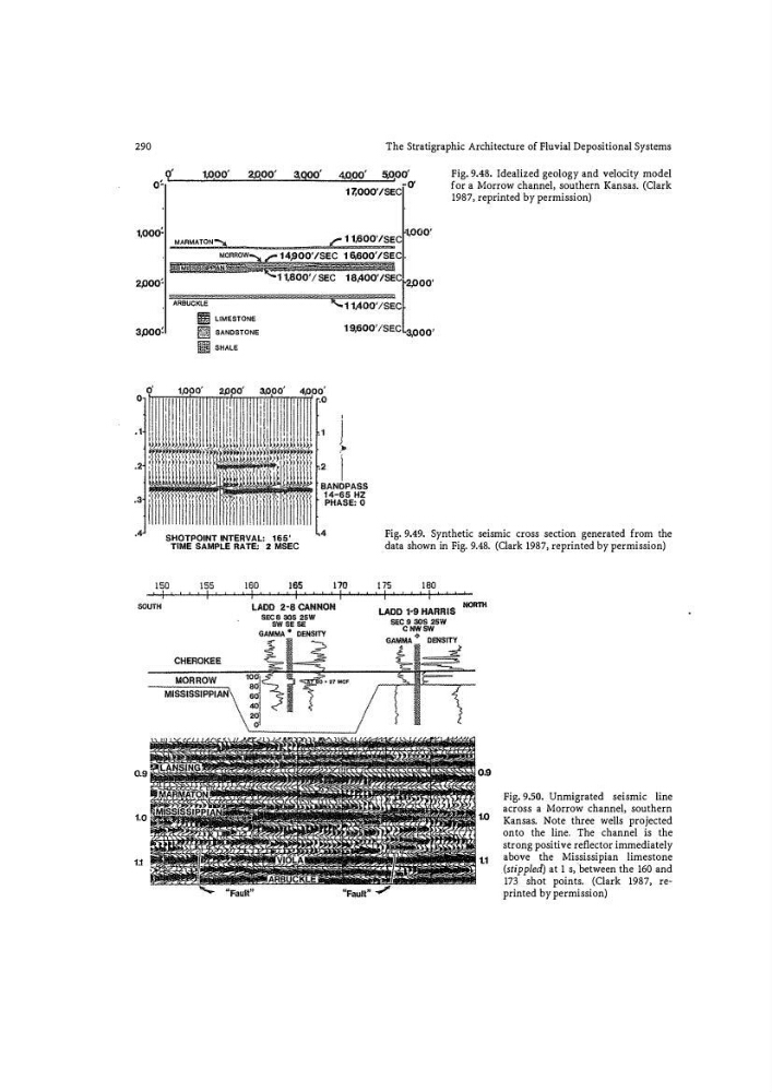
Fig. 9.48. Idealized geology and velocity model
for a Morrow channel, southern Kansas. (Clark
1987, reprinted by permission)
SHOTPOINT INTERVAL: 165'
TIME SAMPLE RATE: 2 MSEC
Fig. 9.49. Synthetic seismic cross section generated from the
data shown in Fig. 9.48. (Clark 1987, reprinted by permission)
0,9
1.0
1.1
Fig. 9.50. Unmigrated seismic line
across a Morrow channel, southern
Kansas. Note three wells projected
onto the line. The channel is the
strong positive reflector immediately
above the Mississipian limestone
(stippled) at 1 s, ·between the 160 and
173 shot points. (Clark 1987, re�
printed by permission)
o'
1,000 '
2,000'
3,000'
The Stratigraphic Architecture of Fluvial Depositional Systems
r
1,0,0 0'
2,0,00 ' 3,000' 4,o oo' s.o,oo'
0'
17,000' /SEC
11600'/
1,000'
MARMATON Jl
C •
SEC
MORROW") c 14,900'/SEC 16, 600'/SEC
$MISS!i§li§A N%4 4
� � '
·
AA
1 1,800' I SEC 1 8,400' /SEC
OO'
ARBUCKLE
g LIMESTONE
m SANDSTONE
1m! SHALE
Fig. 9.48. Idealized geology and velocity model
for a Morrow channel, southern Kansas. (Clark
1987, reprinted by permission)
SHOTPOINT INTERVAL: 165'
TIME SAMPLE RATE: 2 MSEC
Fig. 9.49. Synthetic seismic cross section generated from the
data shown in Fig. 9.48. (Clark 1987, reprinted by permission)
0,9
1.0
1.1
Fig. 9.50. Unmigrated seismic line
across a Morrow channel, southern
Kansas. Note three wells projected
onto the line. The channel is the
strong positive reflector immediately
above the Mississipian limestone
(stippled) at 1 s, ·between the 160 and
173 shot points. (Clark 1987, re�
printed by permission)